5.7 Measuring Optical Amplifier
5-51
5
●
O.BPF BW
O.BPF.BW sets the sets the ASE bandwidth when NF Select is Total.
When determining the noise figure when a narrow optical bandpass
filter is installed, set the filter bandwidth.
When determining the noise figure when a filter is not inserted, set the
ASE bandwidth.
The value set by O.BPF.BW uses items F
2
and F
4
of the NF (Total)
equation described in section 5.7.7.
When O.BPF.BW is set to 0 nm, the noise figure does not include beat
noise (F
2
) between ASE nor the ASE shot noise (F
4
).
●
Pin Loss
This sets the level difference that is the level of the optical signal input
to MS9740B subtracted from the level of the optical signal actually
input to the optical amplifier.
This is used when measuring the optical input (Pin).
●
Pout Loss
This sets the level difference that is the level of the amplified optical
signal input to MS9740B subtracted from the level of the amplified
optical signal actually output by the optical amplifier.
This is used when measuring the optical output (Pout).
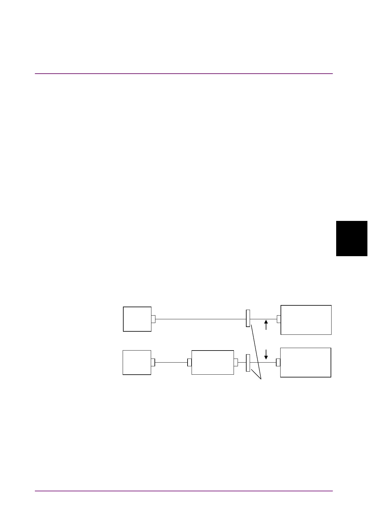
When the optical bandpass filter is installed, Pin and Pout are as
shown below.
●
Pol Loss
This sets the analyzer loss using the polarization nulling method.
This is used when measuring the ASE output (Pase).
If the optical polarization is changed using the polarization controller,
the output level from the analyzer is changed as well. The analyzer loss
is the difference between the maximum value of the analyzer output
level and the output level from the polarization controller.
Source
Amplifier
Analyzer
Source
Analyzer
(b) Measurement of Optical Output