5.7 Measuring Optical Amplifier
5-59
5
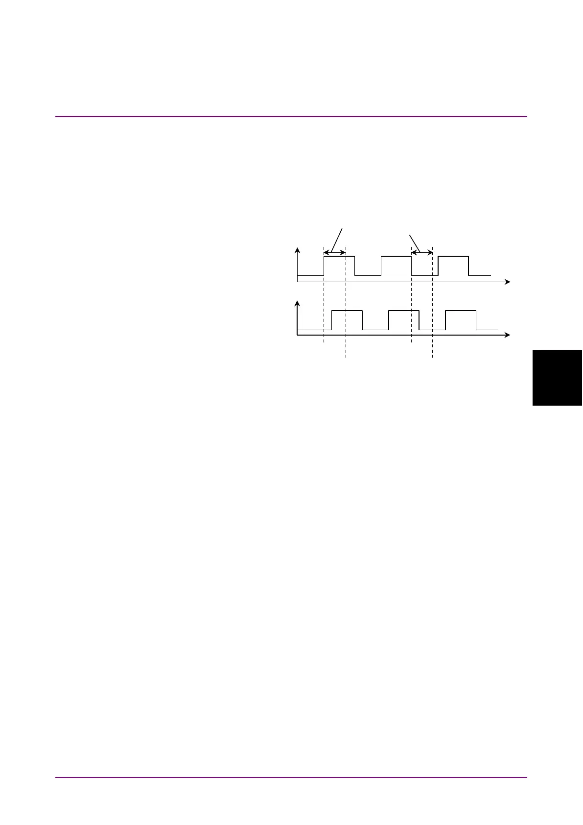
Set the difference between the time when the signal input to the Ext
Trigger connector changes and the time when sampling the optical signal
input to MS9740B as the Ext Trigger Delay.
Measure the signal level Pout after elapse of the Ext Trigger Delay
starting from the Ext Trigger rise, and measure the ASE level Pase after
elapse of the Ext Trigger Delay starting from the Ext Trigger fall.
Figure 5.7.5-2 Definition of Ext Trigger Delay
To perform measurements using the pulse method
1. Press
f1 Method
.
2. Press
f4 Pulse Method
.
3. Press
f7 More 1/2
.
4. Press
f1 Pin
. Select the traces A to J to store the signal waveform.
5. Press
f2 Pout
. Select the traces A to J to store the optical output
waveform.
6. Press
f3 Pase
. Select the traces A to J to store the ASE waveform.
7. Press
f7 More 2/2
.
8. Input the output light of the optical amplifier to MS9740B as shown
by the connection in Figure 5.7.5-1 (a).
Input the modulation signal to the Ext Trigger connector on the rear
panel.
9. Set VBW to a larger value than the modulation frequency.
10. Set the wavelength, resolution, and level scale.
11. Press
f5 Res Cal
.
12.
Press
f1 Execute
. The message indicating the resolution calibration
in progress is displayed.
13. Press
f4 Ext. Trigger Delay
.
14. Adjust the delay time to maximize the optical signal level and press
f8 Back
.
Input
the Optical
Spectrum
Analyzer
Emission