D-7
EvCF
Event configuration bank
Display Item Contents Initial
value
Setting
E1.C1
~
E5.C1
Internal event 1 to 5 Configuration 1 See “Event types.” 0
E1.C2
~
E5.C2
Internal event 1 to 5 Configuration 2
“1st digit” (2nd, etc.) means the first digit (etc.) from the right.
1st digit: Direct/Reverse 0: Direct 1: Reverse 0
2nd digit: Standby 0: None 1: Standby 2: Standby + Standby at SP change 0
3rd digit: EVENT state at READY 0: Continue 1: Forced OFF 0
4th digit: Undefined 0 0
E1.C3
~
E5.C3
Internal event 1 to 5 Configuration 3
“1st digit” (2nd, etc.) means the first digit (etc.) from the right.
1st digit: Alarm OR 0: None 1: Alarm direct + OR operation
2: Alarm direct + AND operation
3: Alarm reverse + OR operation
4: Alarm reverse + AND operation
0
2nd digit: Special OFF 0: As usual
1: When the event set value (main setting) is 0, the event is
"OFF".
0
3rd digit: Delay time unit 0: 0.1 s 1: 1 s 2: 1 min 0
4th digit: Undefined 0 0
dI
DI assignment bank
Display Item Contents Initial
value
Setting
dI1.1 〜 dI5.1
Internal contact 1 to 5 Operation type 0: No function
1: LSP group selection (0/+1)
2: LSP group selection (0/+2)
3: LSP group selection (0/+4)
4: PID group selection (0/+1)
5: PID group selection (0/+2)
6: PID group selection (0/+4)
7: RUN/READY selection
8: AUTO/MANUAL selection
9: Invalid 10: AT execution/stop instructions
11: Invalid 12: Control action direct/reverse
13: SP Ramp enabled/disabled
14: PV Hold
15: PV Maximum value hold
16: PV Minimum value hold
17: Timer Stop/Start
18: Release/continue all DO latches
19: Advance 20: SP Step Hold
0
dI1.2
~
dI5.2
Internal contact 1 to 5 Input bit operation 0: Not used (Default input)
1: Function 1 ((A and B) or (C and D))
2: Function 2 ((A or B) and (C or D))
3: Function 3 (A or B or C or D)
4: Function 4 (A and B and C and D)
0
dI1.3
~
dI5.3
Internal contact 1 to 5 Input assignment
A
0: Normally open (normally off = 0)
1: Normally closed (normally on = 1)
2: DI1 3: DI2 4 to 9: Invalid
10 to 14: Internal event 1 to 5
15 to 17: Invalid 18 to 21: User-defined bit 1 to 4
22: MANUAL 23: READY 24: Invalid
25: AT (Auto-Tuning) 26: During SP ramp
27: Invalid
28: All alarm
29: PV alarm
30: Invalid
31: [MODE] key status
32: Event output 1 terminal status
33: Control output 1 terminal status
0, 2–5
dI1.4
~
dI5.4
Internal contact 1 to 5 Input assignment
B
0
dI1.5
~
dI5.5
Internal contact 1 to 5 Input assignment
C
0
dI1.6
~
dI5.6
Internal contact 1 to 5 Input assignment
D
0
dI1.7
~
dI5.7
Internal contact 1 to 5 Polarity A to D
“1st digit” (2nd, etc.) means the first digit (etc.) from the right.
1st digit: Polarity A 0: Direct
1: Reverse
0
2nd digit: Polarity B 0
3rd digit: Polarity C 0
4th digit: Polarity D 0
dI1.8
~
dI5.8
Internal contact 1 to 5 Polarity 0: Direct 1: Reverse 0
dI1.9
~
dI5.9
Internal contact 1 to 5 Internal event No.
assignment
0: All internal events
1 to 5: Internal event No.
0
dO
DO assignment bank
Display Item Contents Initial
value
Setting
Ot1.1
~
Ot2.1
Ev1.1
~
Ev3.1
Control output 1 to 2, event
output 1 to 3 Operation type
0: Default output
1: MV ON/OFF status 1
2: MV ON/OFF status 2
3 to 6: Function 1 to 4
0
Ot1.2
~
Ot2.2
Ev1.2
~
Ev3.2
Control output 1 to 2, event
output 1 to 3 Output assignment A
0: Normally open (normally off = 0)
1: Normally closed (normally on = 1)
2 to 6: Internal Event 1 to 5
7 to 13: Invalid
14: MV ON/OFF status 1
15: MV ON/OFF status 2
16,17: Invalid 18: DI1 19: DI2 20 to 25: Invalid
26 to 30: Internal contact 1 to 5 31 to 33: Invalid
34 to 37: User-defined bit 1 to 4 38: MANUAL
39: READY 40: Invalid 41: AT (Auto-Tuning)
42: During SP ramp 43: Invalid 44: Alarm
45: PV alarm 46: Invalid 47: [MODE] key status
48: Event output 1 terminal status
49: Control output 1 terminal status
2–4, 14, 15
Ot1.3
~
Ot2.3
Ev1.3
~
Ev3.3
Control output 1 to 2, event
output 1 to 3 Output assignment B
0
Ot1.4
~
Ot2.4
Ev1.4
~
Ev3.4
Control output 1 to 2, event
output 1 to 3 Output assignment C
0
Ot1.5
~
Ot2.5
Ev1.5
~
Ev3.5
Control output 1 to 2, event
output 1 to 3 Output assignment D
0
Ot1.6
~
Ot2.6
Ev1.6
~
Ev3.6
Control output 1 to 2, event output 1 to
3 Polarity A to D
“1st digit” (2nd, etc.) means the first digit (etc.) from the right.
1st digit: Polarity A 0: Direct
1: Reverse
0
2nd digit: Polarity B 0
3rd digit: Polarity C 0
4the digit: Polarity D 0
Ot1.7
~
Ot2.7
Ev1.7
~
Ev3.7
Control output 1 to 2, event
output 1 to 3 Polarity
0: Direct
1: Reverse
0
Ot1.8
~
Ot2.8
Ev1.8
~
Ev3.8
Control output 1 to 2, event
output 1 to 3 Latch
0: None 1: Latch (Latch at ON)
2: Latch (Latch at OFF except for initialization at power ON)
0
UF
User function bank
Display Item Contents Initial
value
Setting
UF-1
~
UF-8
User function 1 to 8 - -
LOC
Lock bank
Display Item Contents Initial
value
Setting
LOC
Key lock 0: All settings can be specified.
1: Mode, event, operation display, SP, UF, lock, manual MV, and
[MODE] key operation can be specified.
2: Operation display, SP, UF, lock, manual MV, and [MODE] key
operation can be specified.
3: UF, lock, manual MV, and [MODE] key operation can be
specified.
0
C.LOC
Communication lock 0: Unlocked 1: Locked 0
L.LOC
Loader lock 0: Unlocked 1: Locked 0
PASS
Password display 0 to 15 (5: Password 1A to 2B display) 0
PS1A
Password 1A 0000 to FFFF (hex) 0000
PS2A
Password 2A 0000 to FFFF (hex) 0000
PS1b
Password 1B 0000 to FFFF (hex) 0000
PS2b
Password 2B 0000 to FFFF (hex) 0000
Id
Instrument information bank
Display Item Contents Initial
value
Setting
Id01
ROM ID 16: Fixed
Not
Applicable
Id02
ROM Version 1
Not
Applicable
Id03
ROM Version 2
Not
Applicable
Id04
Loader information
Not
Applicable
Id05
EST information
Not
Applicable
Id06
Manufacturing date code (year) Subtract 2000 from the year.
Example: "21" means the year 2021.
Not
Applicable
Id07
Manufacturing date code (month, day) Month + day divided by 100.
Example: "12.01" means the 1st day of December.
Not
Applicable
Id08
Serial No.
Not
Applicable
Id09
Model No.
Not
Applicable
Id10
Model Information
Not
Applicable
Id11
Production site code
Not
Applicable
FP01 〜 FP16
Advanced function password 1 to 16 0000 to FFFF (hex) 0000
Precautions for setup
• The type of automatic tuning can be changed by
At.ty
(AT type) in
the extended tuning bank. Specify the setting in accordance with
the control characteristics.
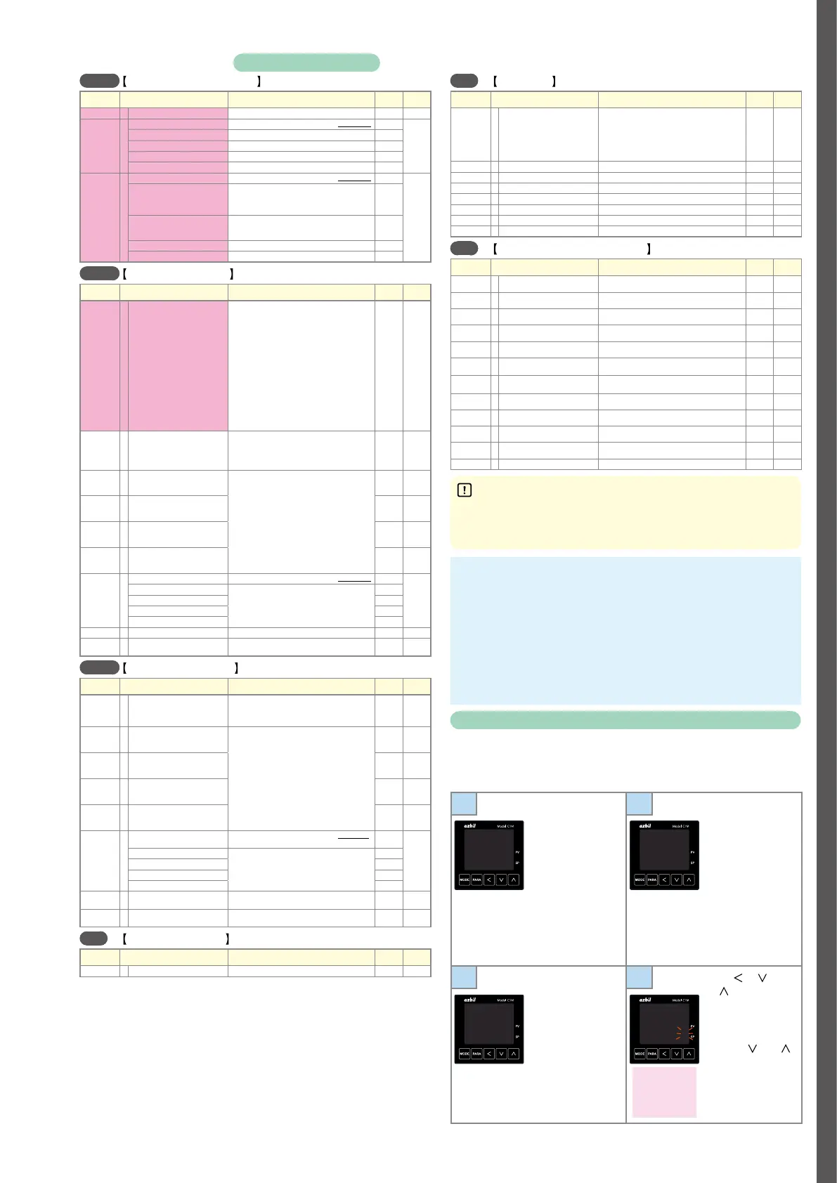
Memo
Changing the user level
The user level can be selected from three options with
C79
. The number
of available displays and settings decreases in the order: advanced
standard
simple. All items are displayed when advanced configuration is
selected.
1
Press [MODE]
once to show the
operation display,
and then hold down
[PARA] for 2 s or
longer.
The screen
for specifying
parameters is
shown with
a--M
or
r--r
on the upper
display.
2
Hold down [PARA]
for 2 s or longer
again.
C01
is shown
on the upper
display.
A--M
AUTO
C 01
1
3
Press [PARA] several
times to change to
c79
(user level).
4
Press [ ], [ ],
or [
]. The lower
display flashes.
Change to the
desired setting by
pressing [
] or [ ].
Do not press any
key for 2 s. The new
value stops flashing
and is now set.
C 79
0
C 79
0002
0: Simple (initial
value)
1: Standard
2: Advanced
Items marked with
in the tables are displayed if standard configuration or advanced configuration is selected for the user level.
To change the user level, see
Changing the user level
at the bottom right of this page.