D-8
PV input range table
Thermocouple RTD
C0
1
Setting
Sensor
type
Range
(Celsius)
Range
(Fahrenheit)
C0
1
Setting
Sensor
type
Range
(Celsius)
Range
(Fahrenheit)
1 K -200 to +1200 °C -300 to +2200 °F 41 Pt100 -200 to +500 °C -300 to +900 °F
2 K 0 to 1200 °C 0 to 2200 °F 42 JPt100 -200 to +500 °C -300 to +900 °F
3 K 0.0 to 800.0 °C 0 to 1500 °F 43 Pt100 -200 to +200 °C -300 to +400 °F
4 K 0.0 to 600.0 °C 0 to 1100 °F 44 JPt100 -200 to +200 °C -300 to +400 °F
5 K 0.0 to 400.0 °C 0.0 to 700.0 °F 45 Pt100
-100.0 to +300.0 °C
-150 to +500 °F
6 K
-200.0 to +400.0 °C
-300 to +700 °F 46 JPt100
-100.0 to +300.0 °C
-150 to +500 °F
9 J 0.0 to 800.0 °C 0 to 1500 °F 51 Pt100 -50.0 to +200.0 °C -50.0 to +400.0 °F
10 J 0.0 to 600.0 °C 0 to 1100 °F 52 JPt100 -50.0 to +200.0 °C -50.0 to +400.0 °F
11 J
-200.0 to +400.0 °C
-300 to +700 °F 53 Pt100 -50.0 to +100.0 °C -50.0 to +200.0 °F
13 E 0.0 to 600.0 °C 0 to 1100 °F 54 JPt100 -50.0 to +100.0 °C -50.0 to +200.0 °F
14 T
-200.0 to +400.0 °C
-300 to +700 °F 63 Pt100 0.0 to 200.0 °C 0.0 to 400.0 °F
15 R 0 to 1600 °C 0 to 3000 °F 64 JPt100 0.0 to 200.0 °C 0.0 to 400.0 °F
16 S 0 to 1600 °C 0 to 3000 °F 67 Pt100 0.0 to 500.0 °C 0.0 to 900.0 °F
17 B 0 to 1800 °C 0 to 3300 °F 68 JPt100 0.0 to 500.0 °C 0.0 to 900.0 °F
18 N 0 to 1300 °C 0 to 2300 °F
DC voltage / DC current
19 PL II 0 to 1300 °C 0 to 2300 °F
20 WRe5-26 0 to 1400 °C 0 to 2400 °F
C0
1
Setting
Sensor
type
Range
21 WRe5-26 0 to 2300 °C 0 to 4200 °F
23 PR40-20 0 to 1900 °C 0 to 3400 °F 84 0 to 1 V The scaling range is -1999
to +9999. The number of
decimal places is changeable.
24 DIN U
-200.0 to +400.0 °C
-300 to +700 °F 86 1 to 5 V
25 DIN L
-100.0 to +800.0 °C
-150 to +1500 °F 87 0 to 5 V
88 0 to 10 V
89 0 to 20 mA
: Initial value 90 4 to 20 mA
Alarm codes
Alarm
code*
1
Description Cause Corrective action
Input errors
AL01
PV input error
(over range)
Sensor burnout, incorrect wiring Check the wiring.
Incorrect settings for PV range type,
etc.
Check the PV range type (C01) and
other settings.
AL02
PV input error
(under range)
Sensor burnout, incorrect wiring Check the wiring.
Incorrect settings for PV range type,
etc.
Check the PV range type (C01) and
other settings.
AL03
Reference junction
compensation (cold junction
compensation) error
Measurement range error in terminal
temperature at reference junction
compensation
Make sure that the ambient
temperature is within the
specifications of this product.
RTD input error Sensor burnout, incorrect wiring Check the wiring.
AL11
Current transformer (CT)
input error (over range)*
2
Current input exceeding the high
limit of the display range
• Use a current transformer with a
number of turns that matches the
display range.
• Check the number of CT turns and
the setting.
• Check the setting and the number
of times the power wire passes
through the CT.
Incorrect wiring Check the wiring.
Instrument errors
AL70
A/D conversion error A/D conversion unit failure Turn the power off and then on
again.
If the alarm is triggered when the
power is turned on again, replace
the device.
AL74
Nonvolatile memory error Temporary communication error,
corruption of data written, or failure
of this device
AL80
Nonvolatile memory not
initialized
AL81
Setting value area error*
3
AL82
Adjustment value area error*
3
AL83
Internal system error
AL84
Setting value initialization
error
Turn the power off and then on
again.
If the alarm is triggered after
turning the power on again, the
problem can be corrected with the
following procedure:
• Initialize the set point
• Write the setting again
If this procedure does not correct
the problem, replace the device.
AL95
Setting value error
AL96
Adjustment value error Turn the power off and then on
again.
If the alarm is triggered after
turning the power on again, the
problem can be corrected with the
following procedure:
• Restore the adjusted value*
4
If
this procedure does not correct
the problem, replace the device.
*1 Multiple alarms may occur at the same time. If the corrective action for one of the alarms says that
the device should be replaced, it should be replaced.
*2 The error occurred because of CT input 1, 2, or both.
*3 This error may occur when updating the firmware.
*4 If the area in memory for restoring the adjustment value has been corrupted, the value cannot be
restored.
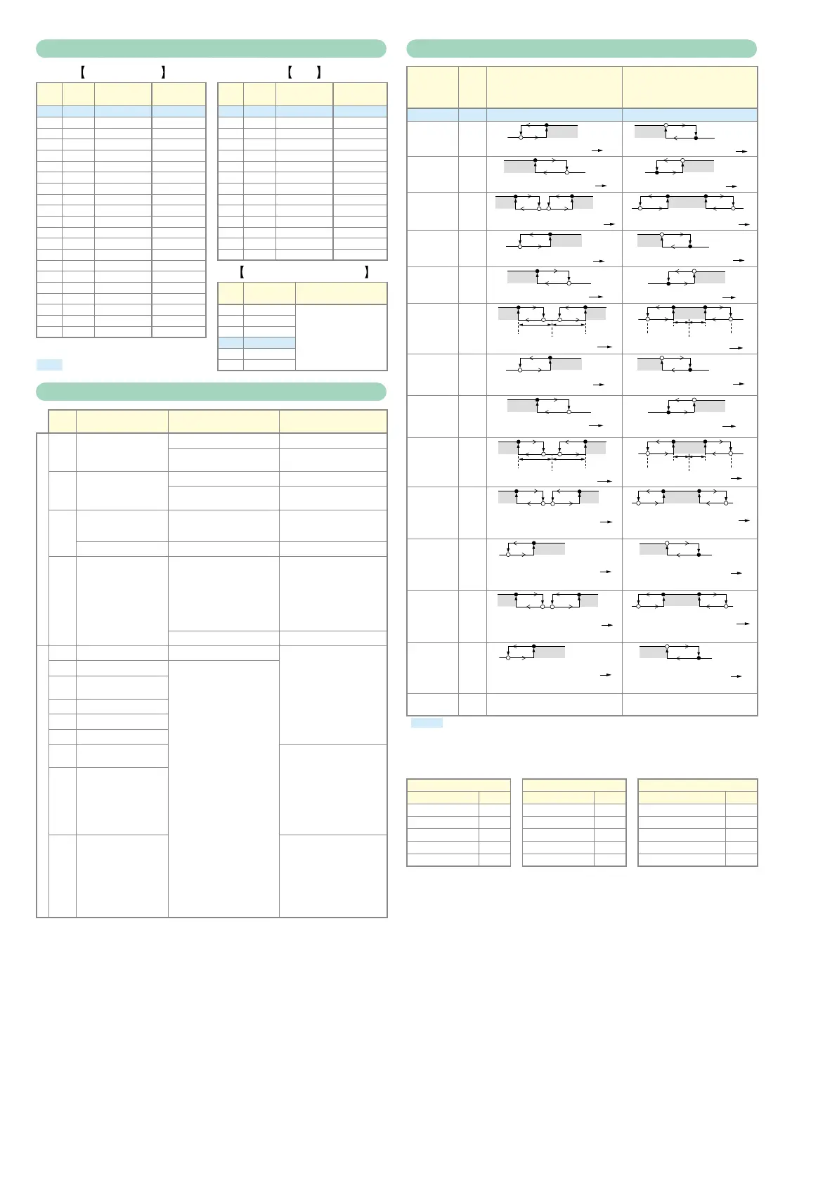
Event types
Operation
type
Setting
Direct action
: ON/OFF changes at the value
: ON/OFF changes when the value
is exceeded
Reverse action
: ON/OFF changes at the value
: ON/OFF changes when the value
is exceeded
No event 0 Always OFF Always OFF
PV high limit 1
ONHYS
Main setting
ON
HYS
Main setting
PV low limit 2
Main setting
ON
HYS
ON
HYS
PV hogh/low
limit
3
* Sub-setting*
ON HYS ONHYS
Main setting* Sub-setting*
ONHYS
HYS
Deviation
high limit
4
ONHYS
SP+Main setting
ON
HYS
SP+Main setting
Deviation
low limit
5
Main setting
ON HYS
SP+Main setting
ONHYS
Deviation
high/low
limit
6
Main
setting
Sub-
setting
SP
ON HYS
ONHYS
ONHYS HYS
Main
setting
Sub-
setting
SP
Deviation
high limit
(Final SP
reference)
7
ONHYS
SP+Main setting
ON
HYS
SP+Main setting
Deviation
low limit
(Final SP
reference)
8
Main setting
ON HYS
SP+Main setting
ONHYS
Deviation
high/low
limit (Final
SP reference)
9
Main
setting
Sub-
setting
ON HYS
ONHYS
ONHYS HYS
Main
setting
Sub-
setting
Heater 1
burnout/
Overcurrent
16
CT1 when output is ON
Main setting*
Sub-setting*
ON HYS
ONHYS
OFF before measuring CT1 current
ONHYS HYS
Sub-setting*
OFF before measuring CT1 current
Heater 1
shortcircuit
17
ON
HYS
Main setting
OFF before measuring CT1 current
ON
HYS
Main setting
OFF before measuring CT1 current
Heater 2
burnout/
Overcurrent
18
CT2 when output is ON
Main setting*
Sub-setting*
ON HYS
ONHYS
OFF before measuring CT2 current
ONHYS HYS
Sub-setting*
OFF before measuring CT2 current
Heater 2
shortcircuit
19
ON
HYS
Main setting
OFF before measuring CT2 current
ON
HYS
Main setting
OFF before measuring CT2 current
Alarm
(status)
23 ON if there is an alarm,
otherwise OFF
OFF if there is an alarm,
otherwise ON
: Initial value
* If the main setting is greater than the sub-setting, operations are performed with the settings
automatically swapped.
Event types other than the above
Operation Operation Operation
Type Setting Type Setting Type Setting
SP high limit 10 MV high/low limit 15 MANUAL (status) 25
SP low limit 11 Loop diagnosis 1 20 AT in execution (status) 27
SP high/low limit 12 Loop diagnosis 2 21 During SP ramp 28
MV high limit 13 Loop diagnosis 3 22 Control action (status) 29
MV low limit 14 READY (status) 24 Timer (status) 32