9-17
Chapter 9. PLC Link Communication Function
9 - 4 List of PLC Link Settings
The PLC link settings include common settings, transfer settings, and data settings.
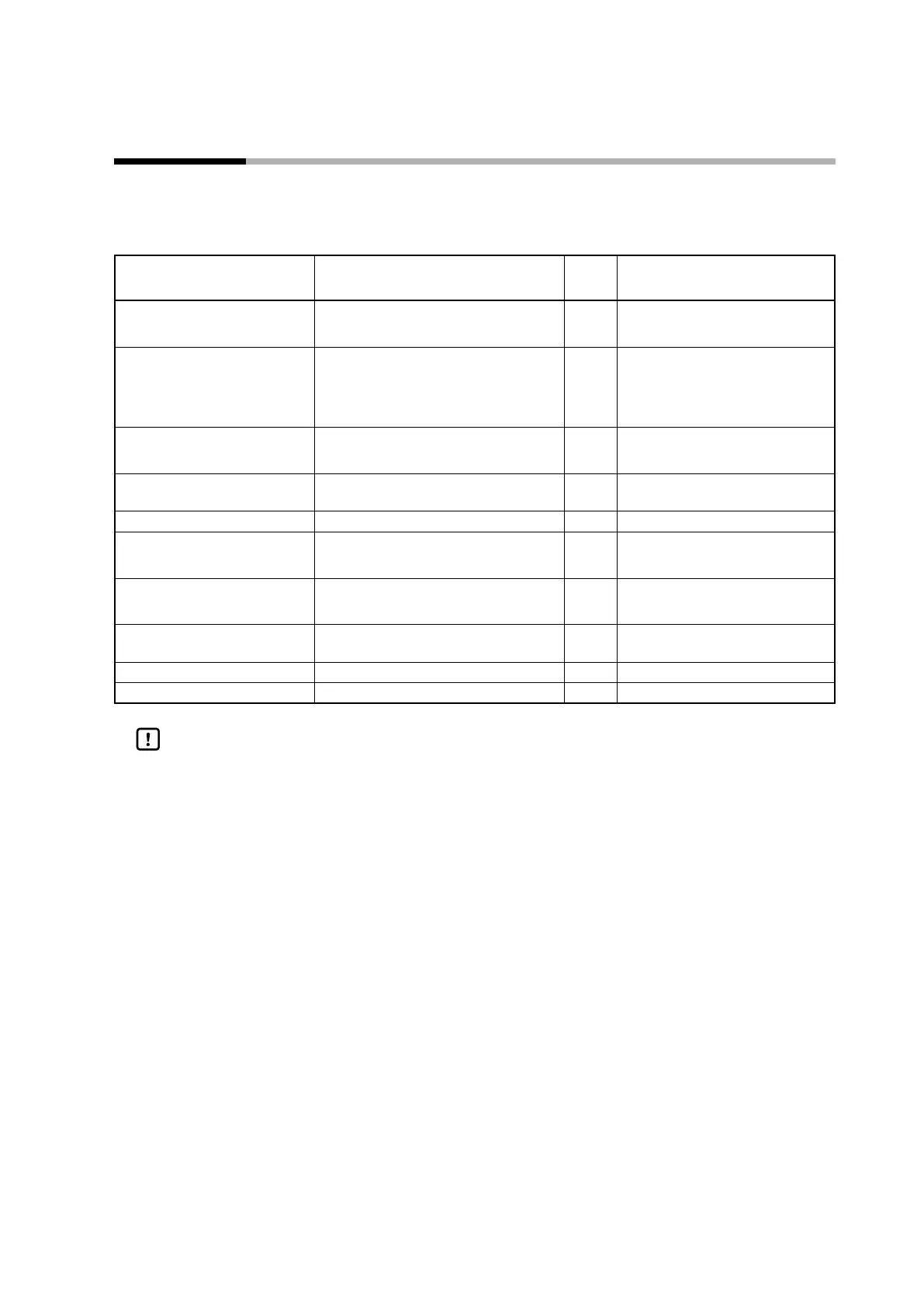
Common settings
Item Settings Initial
value
Notes
PLC Link Function 0: Disabled
1: Enabled
0
PLC Link Operation at Power On 0: PLC link operation stops when the
power is turned on.
1: PLC link operation is executed when
the power is turned on.
0 The setting is valid only if [PLC Link
Function] is set to 1.
PLC Link Operation 0: Stop
1: Execute
0 The setting is valid only if [PLC Link
Function] is set to 1.
Max. No. of units connected by
PLC link
8, 16, 24, 31 8
Startup delay time 0–60 s 5
Trigger device initialization 0: No
1: Yes
0
Notification device initialization 0: No
1: Yes
0
Station address 0–127 0 The address of the PLC to
communicate with
TimeOut 0–32000 ms 1000
Send Delay Time 0–1000 ms 5
Handling Precautions
• When connecting to a Mitsubishi PLC, set the timeout time to 4000 ms or
longer. If a time shorter than 4000 ms is set, faulty communication may result,
depending on the configuration of the Mitsubishi PLC, etc.