11-4
Chapter 11. Maintenance and Troubleshooting
Operation when a PV input error occurs
If a PV input error occurs, this device will operate as follows.
Control output: Whether to continue operation can be specified.
Other operations: Operation continues.
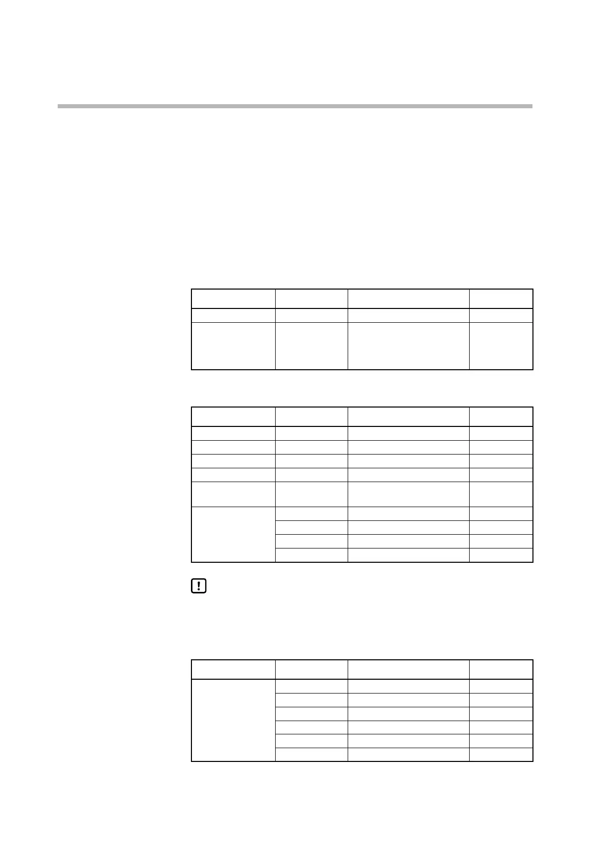
If the PV input is abnormal, this device displays the alarm codes and values shown
in the tables below. What is displayed varies depending on the sensor type.
z
Thermocouple
Error Range No. Indication Alarm code
Sensor burnout Upscale (110 % FS)
AL01
Reference junction
compensation
(cold junction
compensation) error
PV with incorrect cold contact
compensation
AL03
z
Resistance temperature detector (RTD)
Error Range No. Indication Alarm code
Resistor burnout Upscale (110 % FS)
AL01
Line A burnout Upscale (110 % FS)
AL01
Line B burnout Upscale (110 % FS)
AL01, AL03
2- or 3-wire burnout Upscale (110 % FS)
AL01, AL03
Short circuit, lines A
and B
Downscale (−10 % FS)
AL02
Short circuit, lines A
and B
41 (Pt100) −235 °C (−5 % FS)/−235 °F
AL02
42 (JPt100) −235 °C (−5 % FS)/−235 °F
AL02
43 (Pt100) −235 °C (−9 % FS)/−235 °F
AL02
44 (JPt100) −235 °C (−9 % FS)/−235 °F
AL02
Handling Precautions
• If the temperature unit is Fahrenheit, a PV low limit alarm (AL02) is
generated at −235 °F, which is within the PV range, for PV ranges 41–44.
z
DC voltage/current
Error Range No. Indication Alarm code
Burnout 84 (0–1 V) Downscale (−3 % FS)
AL02
86 (1–5 V) Downscale (−10 % FS)
AL02
87 (0–5 V) Downscale (−3 % FS)
AL02
88 (0–10 V) Downscale (0 % FS) None
89 (0–20 mA) Unknown (around 0 % FS) None
90 (4–20 mA) Downscale (−10 % FS)
AL02