4-10
Chapter 4. Wiring
z
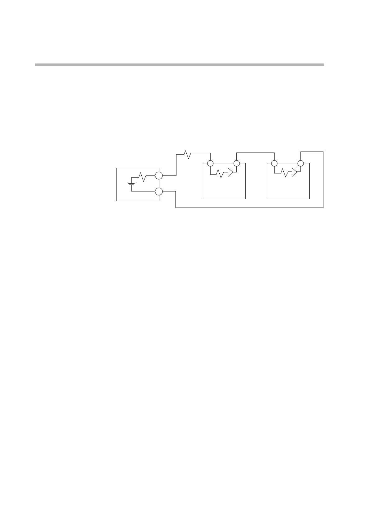
Resistance SSR
Connect an external resistor in series as needed so that the voltage between the
input terminals of the SSR is within the specified range.
Example: when connecting two SSRs
Connection diagram
Model C1M
V
R0
R2
Vf
3 4
R2 Vf
3 4
+
−
When connecting n units of the SSR, the voltage between the terminals of the SSR
can be calculated by the expression below:
((V × R2) + Vf × (R0 + R1)) ÷ (R0 + R1 + n × R2)
When n = 2 and external resistance R1 = 680 Ω, the result is:
V: 19 V ±15 %
R0: 18 Ω ±0.5 %
R1: 680 Ω
R2: 260 Ω
Vf: 1.1 V
Voltage between terminals
= ((19 × 260) +1.1 × (18 + 680)) ÷ (18 + 680 + 2 × 260)
≈ 4.7 V
If the input voltage range of the SSR is 3–6 V, it can operate.