IP Configuration: VRRP
Overview
Cisco 500 Series Stackable Managed Switch Administration Guide 418
20
Constraints
VRRP is only supported on SG500X/ESW2-550X switches.
VRRP Topology
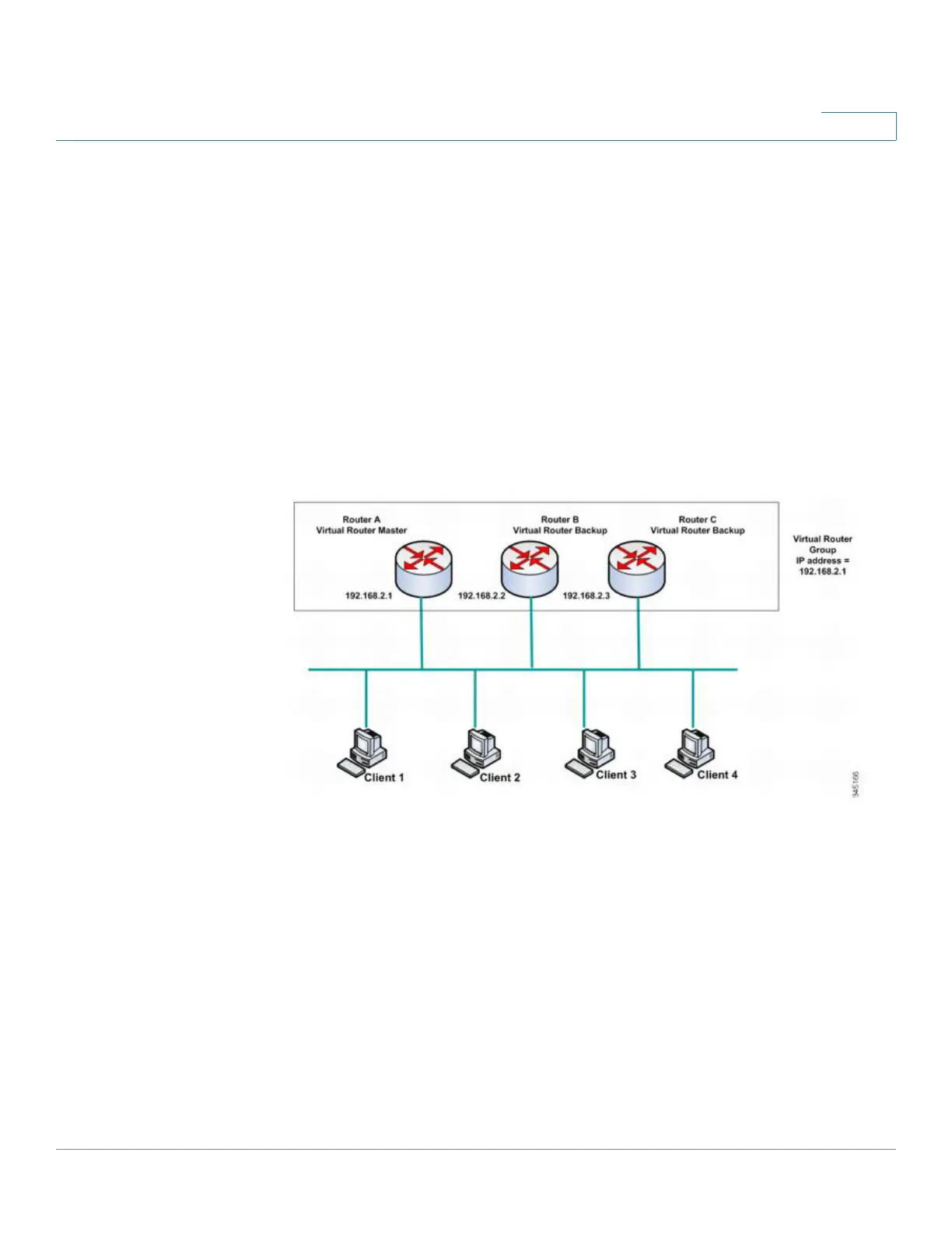
The following shows a LAN topology in which VRRP is configured. In this example,
Routers A, B and C are VRRP and comprise a virtual router. The IP address of the
virtual router is the same as that configured for the Ethernet interface of Router A
(198.168.2.1).
Basic VRRP Topology
Because the virtual router uses the IP address of the physical Ethernet interface of
Router A, Router A assumes the role of the virtual router master and is also known
as the IP address owner. As the virtual router master, Router A controls the IP
address of the virtual router and is responsible to route packets on behalf of the
virtual router. Clients 1 through 3 are configured with the default gateway IP
address of 198.168.2.1. Client 4 is configured with the default gateway IP address
of 198.168.2.2.
NOTE The VRRP router that is the IP address owner responds/processes packets whose
destination is to the IP address. The VRRP router that is the virtual router master, but
not the IP address owner, does not respond/process those packets.
 Loading...