EasyManuals Logo

Cisco 500 Series Administration Guide

Cisco 500 Series
653 pages
To Next Page IconTo Next Page
To Previous Page IconTo Previous Page
Page #422 background imageLoading...
Page #422 background image
IP Configuration: VRRP
Overview
Cisco 500 Series Stackable Managed Switch Administration Guide 420
20
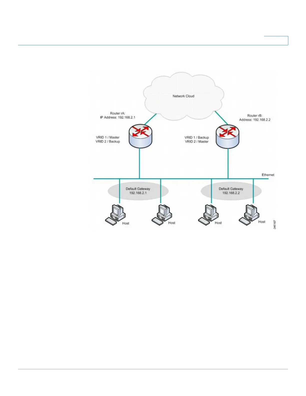
Load Sharing VRRP Topology
In this topology, two virtual routers are configured. For virtual router 1, rA is the
owner of IP address 192.168.2.1 and is the virtual router master, and rB is the
virtual router backup to rA. Clients 1 and 2 are configured with the default gateway
IP address of 192.168.2.1.
For virtual router 2, rB is the owner of IP address 192.168.2.2 and virtual router
master, and rA is the virtual router backup to rB. Clients 3 and 4 are configured with
the default gateway IP address of 192.168.2.2.

Table of Contents

Other manuals for Cisco 500 Series

Questions and Answers:

Question and Answer IconNeed help?

Do you have a question about the Cisco 500 Series and is the answer not in the manual?

Cisco 500 Series Specifications

General IconGeneral
ModelCisco 500 Series
CategorySwitch
MountingRack-mountable
ManagementWeb-based, CLI, SNMP
Ports24, 48
Port Speed10/100/1000 Mbps
PoE SupportAvailable on some models
Switching CapacityUp to 176 Gbps
MAC Address Table Size16, 000 entries
SecurityACLs, 802.1X
Quality of Service (QoS)Yes
DimensionsVaries by model
WeightVaries by model
Humidity10% to 90% non-condensing
Power SupplyInternal
Power ConsumptionVaries by model
Jumbo Frame SupportUp to 9216 bytes

Related product manuals