5-9
Cisco D9865 Satellite Receiver Software Version 2.20 Installation and Configuration Guide
OL-31085-01
Chapter 5 Setup and Monitoring via Web GUI
Setting up Tuning Information
You can set the LNB Power to Off, 18-H, 13-V, H-NIT, or V-NIT. The default is 18-H. If LNB Power is
set to V-NIT or H-NIT, the signal polarization is automatically read from the NIT. Power will not be
applied to the LNB if LNB Power is set to Off.
Note LNB power must be on if DiSEqC is required. For more information, see LNB Power Settings,
page 4-21.
Step 8 In the Network ID field, enter the network ID of the uplink signal the receiver is to receive when using
this preset. You can obtain the network ID from your service provider. The default is 1.
Step 9 In the LO Freq 1 field, enter the Local Oscillator Frequency #1 that sets the satellite antenna LNB local
oscillator #1 frequency. For C-Band application, set to 5.15 GHz. For Ku-band single LNB, enter LO
Freq and set LO Freq 2 and Crossover Frequency to 0.0. For Ku-band dual LNB, enter LO Freq 1, LO
Freq 2 and Crossover Frequency. The default is 10.75 GHz.
Step 10 In the LO Freq 2 field, enter the Local Oscillator Frequency #2 that sets the satellite antenna LNB local
oscillator #2 frequency. This option is only used in dual-band LNB applications. LO Freq 2 must be
greater than LO Freq 1. The default is 0.0 GHz.
Step 11 In the Crossover Frequency field, enter the internal threshold frequency used for selecting the LO1 or
LO2 frequency, depending on the current downlink frequency settings. This option is only used in
dual-band LNB applications. The default is 0.0 GHz.
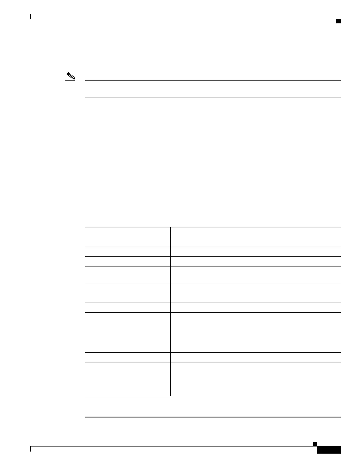
Step 12 The Current Input Status area displays the current RF status. The following table describes the Current
Input Status information displayed:
Step 13 Click Apply.
RF Status Description
Downlink Frequency Indicates the current downlink frequency, in GHz.
L Band Frequency (MHz) Indicates the current L-Band frequency, in MHz.
Symbol Rate (Msym) Indicates the Symbol Rate of the received signal, in MS/s.
FEC Indicates the FEC (Forward Error Correction) rate of the received
signal.
Modulation Type Indicates the modulation type for the received signal.
Pilots Indicates whether the pilots for the DVB-S2 modulation is on or off.
I/Q Indicates the input signal spectrum inversion setting.
Signal Status Indicates the current signal lock status for the input.
Locked - Receiver is locked to a carrier with no valid content.
Lock+Sig - Receiver is locked to a carrier with valid content.
No Lock - Receiver is not locked to a carrier.
TS ID Displays the Transport Stream ID.
LNB Presets Indicates the number of LNB presets configured.
Acquisition State Displays Full if the ASI and PSI tables have all been found.
Otherwise, it will display Degraded if there are missing tables or
None if no ASI or PSI tables have been found.