4.4.4 Rapid Spanning Tree
The Spanning Tree Protocol (STP), defined in the IEEE Standard 802.1D, creates a spanning tree
within a mesh network of connected layer-2 bridges (typically Ethernet switches) and disables the
links which are not part of that tree, leaving a single active path between any two network nodes.
Multiple active paths between network nodes cause a bridge loop. Bridge loops create several
problems. First, the MAC address table used by the switch or bridge can fail, since the same MAC
addresses (and hence the same network hosts) are seen on multiple ports. Second, a broadcast
storm occurs. This is caused by broadcast packets being forwarded in an endless loop between
switches. A broadcast storm can consume all available CPU resources and bandwidth.
Spanning tree allows a network design to include spare (redundant) links to provide automatic
backup paths if an active link fails, without the danger of bridge loops, or the need for manually
enabling/disabling these backup links.
To provide faster spanning tree convergence after a topology change, an evolution of the
Spanning Tree Protocol: Rapid Spanning Tree Protocol (RSTP), introduced by IEEE with
document 802.1w. RSTP, is a refinement of STP; therefore, it shares most of its basic operation
characteristics. This essentially creates a cascading effect away from the root bridge where each
designated bridge proposes to its neighbors to determine if it can make a rapid transition. This is
one of the major elements which allows RSTP to achieve faster convergence times than STP.
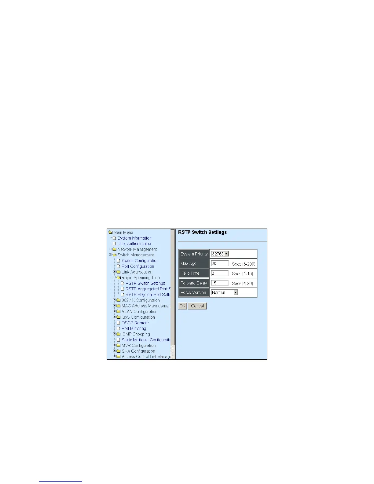
Click the folder Rapid Spanning Tree from the Switch Management menu and then three
options within this folder will be displayed as follows.
1. RSTP Switch Settings: Set up system priority, max Age, hello time, etc.
2. RSTP Aggregated Port Settings: Set up aggregation, path cost, priority, edge, etc.
3. RSTP Physical Port Settings: Set up physical, ability and edge status of port.
 Loading...