2. Enter the appropriate information in the form as described below:
Select On Line, Continuous, or PackTrack from the Operating Mode
Selection drop-down list.
Select 1 Input Used, 2 Inputs Used, or Serial from the On Line Options drop-
down list. Each selection has a different set of parameters as described below. In
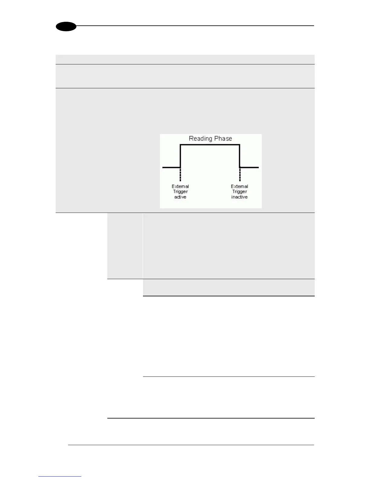
this operating mode, the reading phase is defined as the time between the Phase
ON and Phase OFF events. The Phase events can be signals coming from one
or two external presence sensors connected to the scanner inputs or serial
start/stop strings sent from the host over the serial interface or Ethernet input.
The reading phase takes place during the active phase of the
presence sensor, when the scanner tries to acquire and correctly
decode the code. If the operation is successful, the barcode
characters are transmitted on the serial interface or Ethernet input
in the format defined by the current configuration and the right
output event is raised at the end of the photoelectric sensor’s active
phase. If a code cannot be decoded, a no read message is sent
and the no read event is raised at the end of the photoelectric
sensor’s active phase.
This parameter is available only for Fieldbus
Hosts and if checked, allows the Fieldbus Master
to drive the Reading Phase.
For Profinet or Profibus interfaces, it allows the
Fieldbus Master to drive the reading phase via bit
7 in Byte 0 (LSB) of the Output Area.
For EtherNet/IP, it allows the EtherNet/IP Client to
drive the reading phase via bit 7 in Byte
OutputBits of the DL_OutputStruct.
Select the Input Number from the selections
available in the drop-down list.
This option defines the numbered input that will
start the trigger cycle.