ID-NET SYNCHRONIZED NETWORK
PRODUCT REFERENCE GUIDE
105
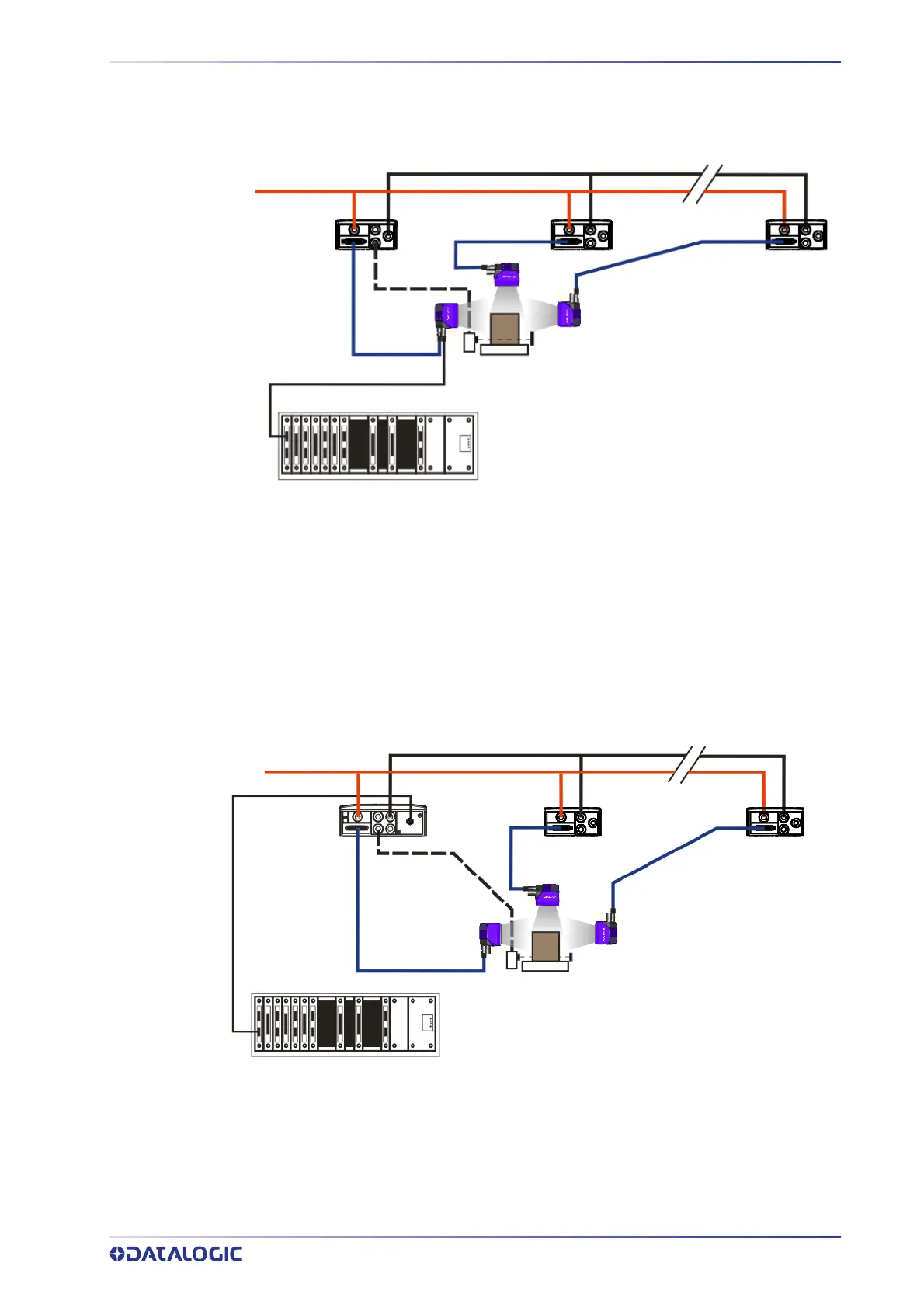
The same configuration can be made to a Host using the on-board Ethernet interface to
the Master. The TCP/IP Ethernet and ID-NET interfaces are connected as shown in the
figure below.
Host
Power
ID-NET
Master
Synchronized
ID-NET
Slave#1
Synchronized
ID-NET
Slave#n
Synchronized
TCP/IP on-board Ethernet Interface
External Trigger
ID-NET (up to 16 devices - practical limit)
CBX100
Figure 84 - ID-NET Synchronized Layout with Master on-board TCP/IP Ethernet
Interface to Host
Alternatively, the Master reader can communicate to the Host as a Slave node on a
Fieldbus network. This requires using an accessory Fieldbus interface board installed
inside the CBX500 connection box. System configuration can be accomplished through
the Ethernet interface of each individual reader using the DL.CODE configuration pro-
gram.
Host
Power
ID-NET
Master
Synchronized
ID-NET
Slave#1
Synchronized
ID-NET
Slave#n
Synchronized
Fieldbus Interface
External Trigger
ID-NET (up to 16 devices - practical limit)
CBX500
Figure 85 - ID-NET Synchronized Layout with Master CBX500 Fieldbus Interface to Host