Home
Emerson
Controller
FloBoss S600+
Emerson FloBoss S600+ User Manual
5
of 1
of 1 rating
156 pages
Give review
Manual
Specs
To Next Page
To Next Page
To Previous Page
To Previous Page
Loading...
S600+ Instruction
Manual
4-2
I/O
Revised July-201
7
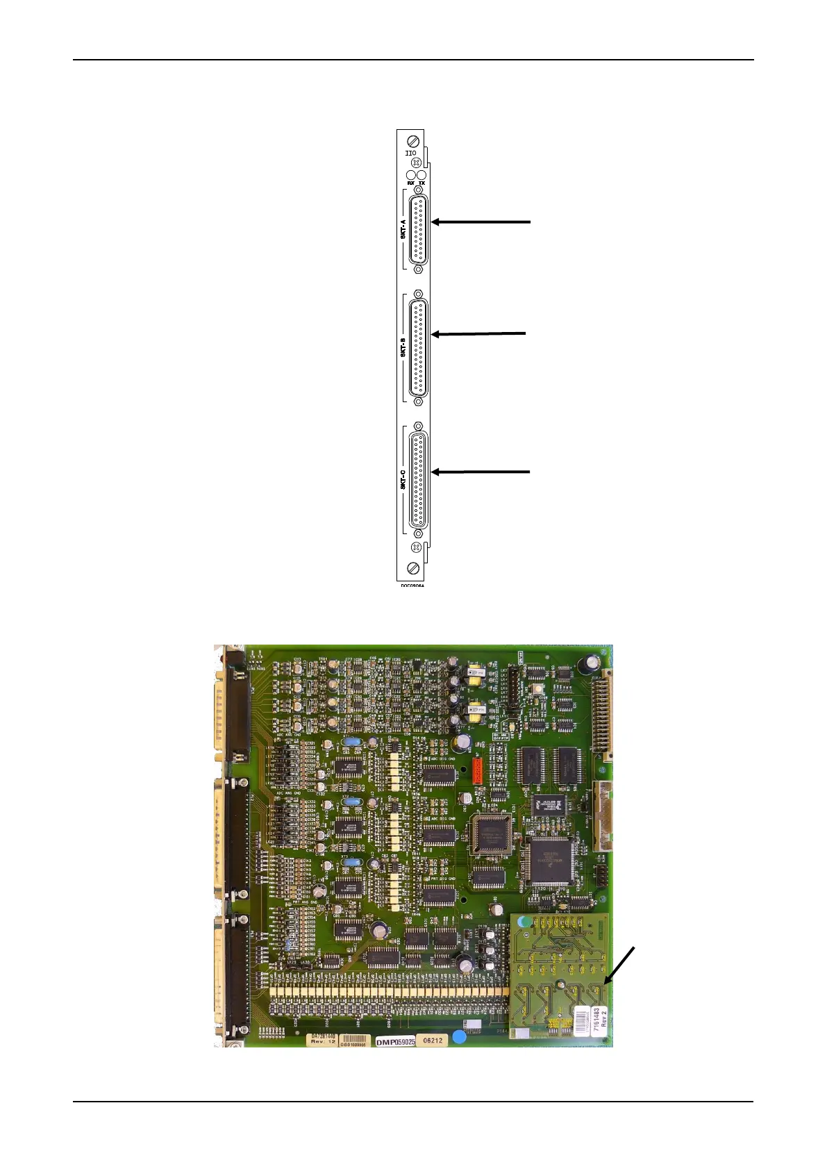
For field wiring, the module provides three low-density D-type
connectors
:
SKT-A, SKT-B, and SKT-C (refer to
Figure 4-1
).
Figure 4-1. I/O Module (P144)
Figure 4-2. Example I/O Module (with Mezzanine Modul
e)
SKT
-A
ANIN 1-
10
ANOUT 1-4
SKT
-C
DIGIN 7-16
DIGOUT 3-
12
Turbine Inputs
SKT
-B
ANIN 11-
12
DIGIN 1-6
DIGOUT 1-2
Freq Inputs
Pulse Outputs
Mezzan
ine
module (P148)
39
41
Table of Contents
Table of Contents
3
S600
4
Start
4
Troubleshooting
4
Chapter 1 - General Information
7
Scope of Manual
7
Jumpers
7
Disp
7
Print
7
S600
7
Floboss S600+ Flow Computer
8
Config600 Configuration Software
11
Config600 Lite
12
Config600 Lite Plus
12
Config600 Pro
13
Additional Technical Information
14
Open Source Software
14
Chapter 2 - Installation
15
Preparing for Installation
15
Rom
15
Environmental Considerations
16
Required Tools for Installation
16
Installing the S600
17
Unpacking the S600
17
Removing the Front Panel
17
Installing the Panel-Mounted Unit
20
Reinstalling the Front Panel
22
Installing and Removing Modules
22
Installing EMC Protection
24
Module Ready for Removal or Insertion
24
Security Backplate in Place
26
Clamps on CPU Module Power & COM Connections
27
Clamps on CPU Module COM and Ethernet Connections
28
Chapter 3 - CPU Module
29
Port
30
Power Supply
32
Watchdog Relay
32
On-Board Battery Backup
32
Communication Ports
33
Serial Port
34
Ethernet
34
Pin Connections
34
Rts
34
RS-422/RS-485 Multi-Drop Port
35
Ethernet LAN Ports
35
COM5, COM6, and COM7 Pin Connections
35
Local Operator PC or Remote Display Port
36
Link Cable
36
CPU Connectors and Jumpers
37
USB Port
37
CPU Jumpers
37
Additional Technical Information
38
Chapter 4 - Input/Output (I/O)
39
I/O Module (P144)
39
Anin
40
Digin
40
Digout
40
Turbine
40
Pulse Outputs
40
Skt-A
40
Skt-C
40
(Skt-B)
40
Analogue Inputs (ANIN)
41
Dac
41
Prt
41
Skt C
41
Skt B
41
Analogue Input Schematic
42
Analogue Outputs (DAC)
43
Analogue Output Schematic (S600+-Powered)
43
Function
43
Pin Connections
43
Digital Inputs (DIGIN)
44
Analogue Output Schematic (Externally Powered Device)
44
Analogue Output Schematic (Externally Powered through S600+)
44
D/A Converter Output Pin Connections
44
Digital Input Schematic (Open Collector Device)
45
Digital Input Schematic (Relay)
45
Digital Outputs (DIGOUT)
46
Digital Output Schematic (Relay)
46
Digital Output Schematic (24 V Switched Indicator)
46
Turbine Pulse Inputs
47
Port
47
Pulse Outputs (PULSEOUT)
48
Pulse Input Schematic (with -12 V P148 Mezzanine Module)
48
Pulse Input Schematic (with 24 V P148 Mezzanine Module)
48
Pulse Output Schematic
48
Dual Pulse Input Pin Connections
48
Raw Pulse Output (RAWOUT)
49
Raw Pulse Output Schematic
49
Pulseout
49
PULSEOUT Pin Connections
49
Frequency Inputs
50
Frequency Input Schematic (with IS Barrier and AC-Coupled)
50
Raw Pulse Output Pin Connections
50
PRT/RTD Inputs
51
Jumper Settings
52
PRT/PRD Input Pin Connections
52
I/O
53
Prover Module (P154)
54
(Skt-D)
54
Digital Inputs (DIGIN)
56
Pulse out 2
56
Skt F
56
(Skt-E)
56
Digital Input Schematic (Open Collector Device)
57
Digital Input Schematic (Relay)
57
Digital Outputs (DIGOUT)
58
Digital Output Schematic (Relay)
58
Turbine Pulse Inputs
59
Digital Output Schematic (24 V Switched Indicator)
59
Pulse Outputs (PULSEOUT)
60
Frequency Inputs
60
Pulse Input Schematic (with 24 V P148 Mezzanine Module)
60
Pulse Output Schematic
60
PULSEOUT Pin Connections
60
Transducer
60
Frequency Input Schematic (Without IS Barrier and DC-Coupled)
61
Frequency Input Pin Connections
61
Jumper Settings
62
Open Collector
62
HART Module (P188)
63
HART Module
63
Port
63
HART Pin Connections (Socket A)
63
HART Pin Connections (Socket B)
64
Mezzanine Module (P148)
65
HART Device
65
Chapter 5 - Front Panel
67
Description
67
Led
67
Front Panel Port
68
Keypad
68
Function Keys (F1 - F4)
68
Front Panel Port Connector
68
Front Panel Port Connections
68
Direction and Menu Keys
69
Numeric Keys
69
Operation Keys
69
Menu Keys
69
Alarm LED and Alarm Keys
70
LCD Display
70
Editable Value
71
S600+ Main Menu
71
Page Reference Number
71
Status/ID Line
71
Webserver Mode
71
Navigating the Displays
72
Progression of S600+ Menus and Data Page
72
S600+ Main Menu
73
Data Display
73
DISP Key
74
Moving through the Menus
74
Menu Hierarchy
75
Security Codes
75
Changing a Display Option
75
Changing a Display Value
76
Changing a Calculation Mode
77
Assigning a Default Page
77
Assigning a Page to a Function (F) Key
78
Using the Exponential (EXPT) Key
78
Using the Print Key
79
Security Dump
79
Enabling USB
80
Exporting Reports (USB)
80
Event Log
80
USB Report Control Menu
81
Selecting a Configuration
82
Chapter 6 - Webserver Access
85
Defining Webserver Access
85
Accessing the S600
86
Hierarchy Menu
88
Navigating the Webserver Interface
89
Webserver Access (Report Format)
89
Alarm Archive
90
Chapter 7 - Startup
93
Starting the S600
93
Warm Start
93
Cold Start
94
Initiating a Cold Start
94
Startup Menu
95
Network Setup
96
Modbus Screen
98
Messages
99
Chapter 8 - Troubleshooting
101
Guidelines
101
Checklists
102
Power Issues
102
Startup Menu
102
Front Panel Lighting
102
Front Panel LED
102
I/O Led
103
I/O Fail Messages
103
Serial Communications
103
Procedures
103
Reflash Firmware
104
Send and Reflash the Config File
104
Flash Failed
104
Clear SRAM
105
Changing the Fuse
106
Fuse Location
106
Appendix A - Glossary
107
Flash Memory
109
Flow Balance
109
Holding Register
110
Meter Linearisation
110
Non-Volatile Memory
111
Off-Line
111
On-Line
111
Opto-Isolator
111
Peer-To-Peer Link
111
Prove Sequence
111
Security Code
112
Tri-Reg
113
Appendix B - Front Panel Navigation
116
Main Menu
116
Flow Rates Menu
116
Totals Menu
117
Operator Menu
118
Flow Switching
118
Plant I/O Menu
119
System Settings Menu
119
Hart
119
Prt/Rtd
119
Pulse Inputs
119
Tech/Engineer Menu
120
Modbus
120
Print
120
Serial Port
120
Tcp/Ip
120
Calculations Menu
121
Iso 5167
121
Iso 6976
121
Appendix C - Chromatographs
123
Station/Stream Assignment
124
Single Metering Stream with no Station
124
Multiple Metering Streams Assigned to a Common Station
124
Individual Metering Streams Assigned to a Chromatograph
124
Chromatograph
124
Multiple Metering Streams Separately Assigned to a Stream
125
Multiple S600+S Connected to a Single Chromatograph
125
Inputs and Outputs
125
Main Setup Parameters
126
Component Set Selection Inputs
126
Component Set Selection Outputs
126
Telemetry Configuration Parameters
126
Telemetry Outputs
127
Configuration Type: Keypad Mole Percentage Set Only
128
Configuration Type: 2551/2350 Euro
129
Telemetry Stages
129
Determining the Mole Percentage Set
133
Handling Operator Commands
133
Configuration Type: 2251/2350 USA
133
Telemetry Stages
134
Determining the Mole Percentage Set
135
Handling Operator Commands
136
Configuration Type: Siemens
136
Telemetry Stages
136
Determining the Mole Percentage Set
138
Handling Operator Commands
139
Configuration Type: Generic
139
Telemetry Stages
139
Determining the Mole Percentage Set
141
Handling Operator Commands
142
Configuration Type: Download from Supervisory System
142
Normalisation, Additionals, and C+6 Handling
142
Normalisation
142
Application of Additionals
143
C6+ Handling
143
C6+ Handling (SIM 2251 Method
143
C7+ Handling
144
No C6+ or C7+ Handling
145
Alarms, Displays, Reports, and Maps
145
Alarms
145
Displays
145
Reports
146
Modbus Maps
149
Index
151
S600+ Instruction Manual
156
Other manuals for Emerson FloBoss S600+
Field Upgrade Guide
18 pages
Specification Manual
30 pages
5
Based on 1 rating
Ask a question
Give review
Questions and Answers:
Need help?
Do you have a question about the Emerson FloBoss S600+ and is the answer not in the manual?
Ask a question
Emerson FloBoss S600+ Specifications
General
Brand
Emerson
Model
FloBoss S600+
Category
Controller
Language
English
Related product manuals
Emerson FloBoss 107
152 pages
Emerson FL
16 pages
Emerson TARTARINI FL Series
52 pages
Emerson FPCSK
43 pages
Emerson FISHER 67
12 pages
Emerson FISHER 657
32 pages
Emerson FISHER 92S
24 pages
Emerson Fisher 656
12 pages
Emerson Fisher 67C
12 pages
Emerson Fisher 95L
16 pages
Emerson Fisher R622
8 pages
Emerson Fisher 1051
32 pages