EasyManuals Logo

Emerson FloBoss S600+ User Manual

Emerson FloBoss S600+
156 pages
To Next Page IconTo Next Page
To Previous Page IconTo Previous Page
Page #44 background imageLoading...
Page #44 background image
S600+ Instruction Manual
4-6 I/O Revised July-2017
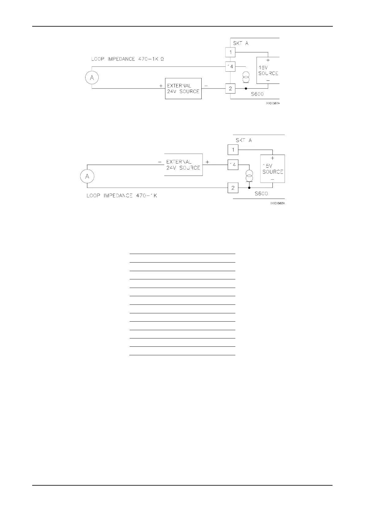
Figure 4-7. Analogue Output Schematic (Externally Powered Device)
Figure 4-8. Analogue Output Schematic (Externally Powered through S600+)
Table 4-3. D/A Converter Output Pin Connections for SKT-A
Pin
Function
1
DAC-CH1 +15 V SOURCE
14
DAC-CH1 SINK
2
DAC-CH1 0 VDC
15
DAC-CH2 +15 V SOURCE
3
DAC-CH2 SINK
16
DAC-CH2 0 VDC
4
DAC-CH3 +15 V SOURCE
17
DAC-CH3 SINK
5
DAC-CH3 0 VDC
18
DAC-CH4 +15 V SOURCE
6
DAC-CH4 SINK
19
DAC-CH4 0 VDC
4.1.3 Digital Inputs (DIGIN)
Each plug-in module provides 16 optically isolated digital inputs
(DIGIN). The digital inputs have been grouped into four banks of 4-off
single-ended inputs with one common feed. Refer to Figures 4-9 and
4-10.
The sample period is less than 1 second.
The DIGIN channels use the connectors labeled SKT-B and SKT-C,
which are located on the backplate of the I/O module. Refer to Tables
4-4 and 4-5 for the DIGIN pin connections.

Table of Contents

Other manuals for Emerson FloBoss S600+

Questions and Answers:

Question and Answer IconNeed help?

Do you have a question about the Emerson FloBoss S600+ and is the answer not in the manual?

Emerson FloBoss S600+ Specifications

General IconGeneral
BrandEmerson
ModelFloBoss S600+
CategoryController
LanguageEnglish

Related product manuals