EasyManuals Logo

Emerson FloBoss S600+ User Manual

Emerson FloBoss S600+
156 pages
To Next Page IconTo Next Page
To Previous Page IconTo Previous Page
Page #50 background imageLoading...
Page #50 background image
S600+ Instruction Manual
4-12 I/O Revised July-2017
Table 4-10. Raw Pulse Output Pin Connections for SKT-C
Pin
Function
24
Raw Output
5
Return
4.1.8 Frequency Inputs
The S600+ typically uses the three supported frequency inputs for
density transducer signals. Each input has an input range of 0 to 10
KHz. Jumpers on the module enable you to set the inputs to be AC- or
DC-coupled. Refer to Figures 4-17 and 4-18.
The frequency input channels use the SKT-B connector, which is
located on the backplate of the I/O module. Table 4-11 shows the
frequency input pin connections.
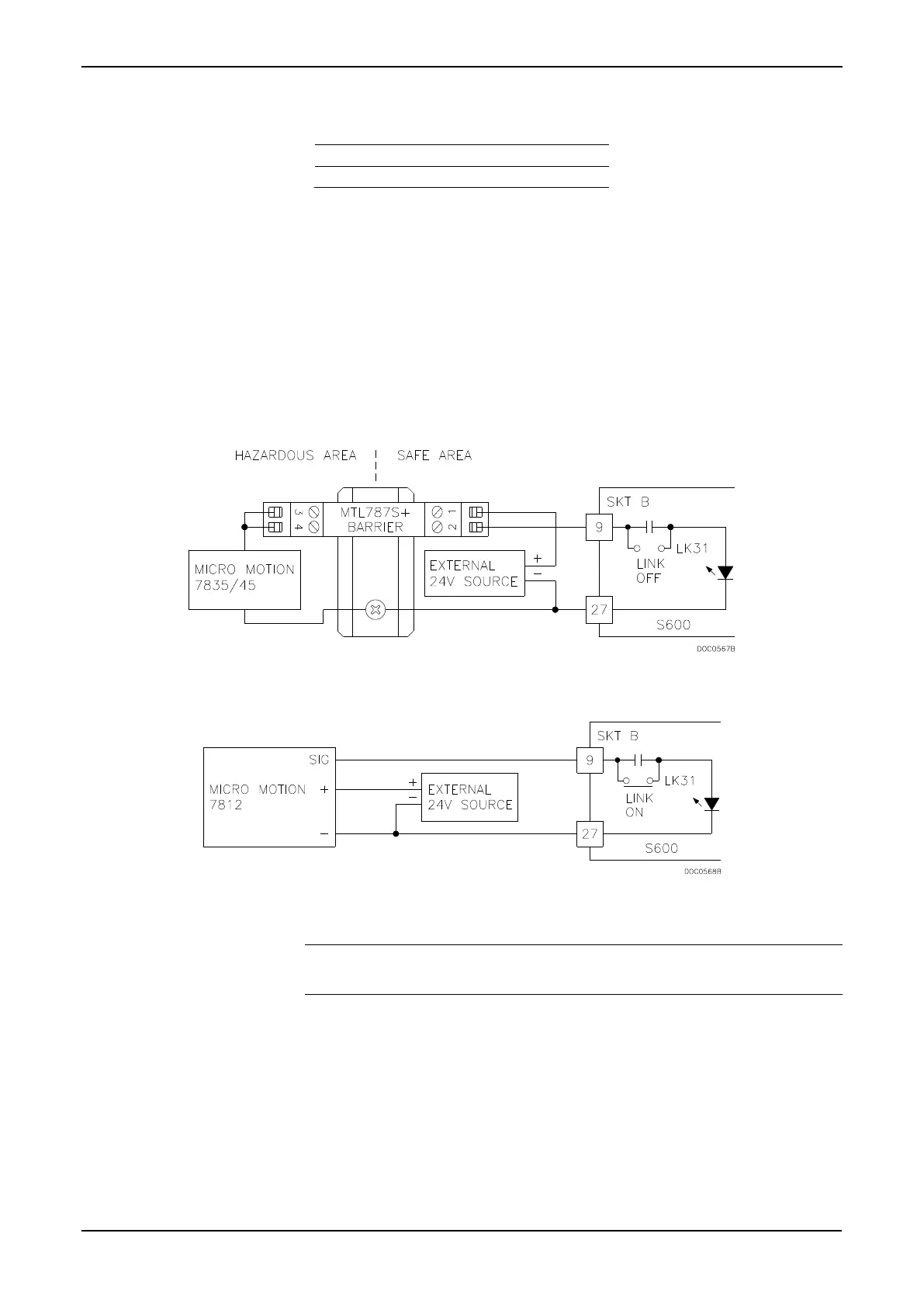
Figure 4-17. Frequency Input Schematic (with IS Barrier and AC-Coupled)
Figure 4-18. Frequency Input Schematic (without IS Barrier and with DC-Coupled)
Note: The Micro Motion (previously Solartron) devices may still
have their previous manufacturer’s labels.

Table of Contents

Other manuals for Emerson FloBoss S600+

Questions and Answers:

Question and Answer IconNeed help?

Do you have a question about the Emerson FloBoss S600+ and is the answer not in the manual?

Emerson FloBoss S600+ Specifications

General IconGeneral
BrandEmerson
ModelFloBoss S600+
CategoryController
LanguageEnglish

Related product manuals