EasyManuals Logo

Emerson FloBoss S600+ User Manual

Emerson FloBoss S600+
156 pages
To Next Page IconTo Next Page
To Previous Page IconTo Previous Page
Page #48 background imageLoading...
Page #48 background image
S600+ Instruction Manual
4-10 I/O Revised July-2017
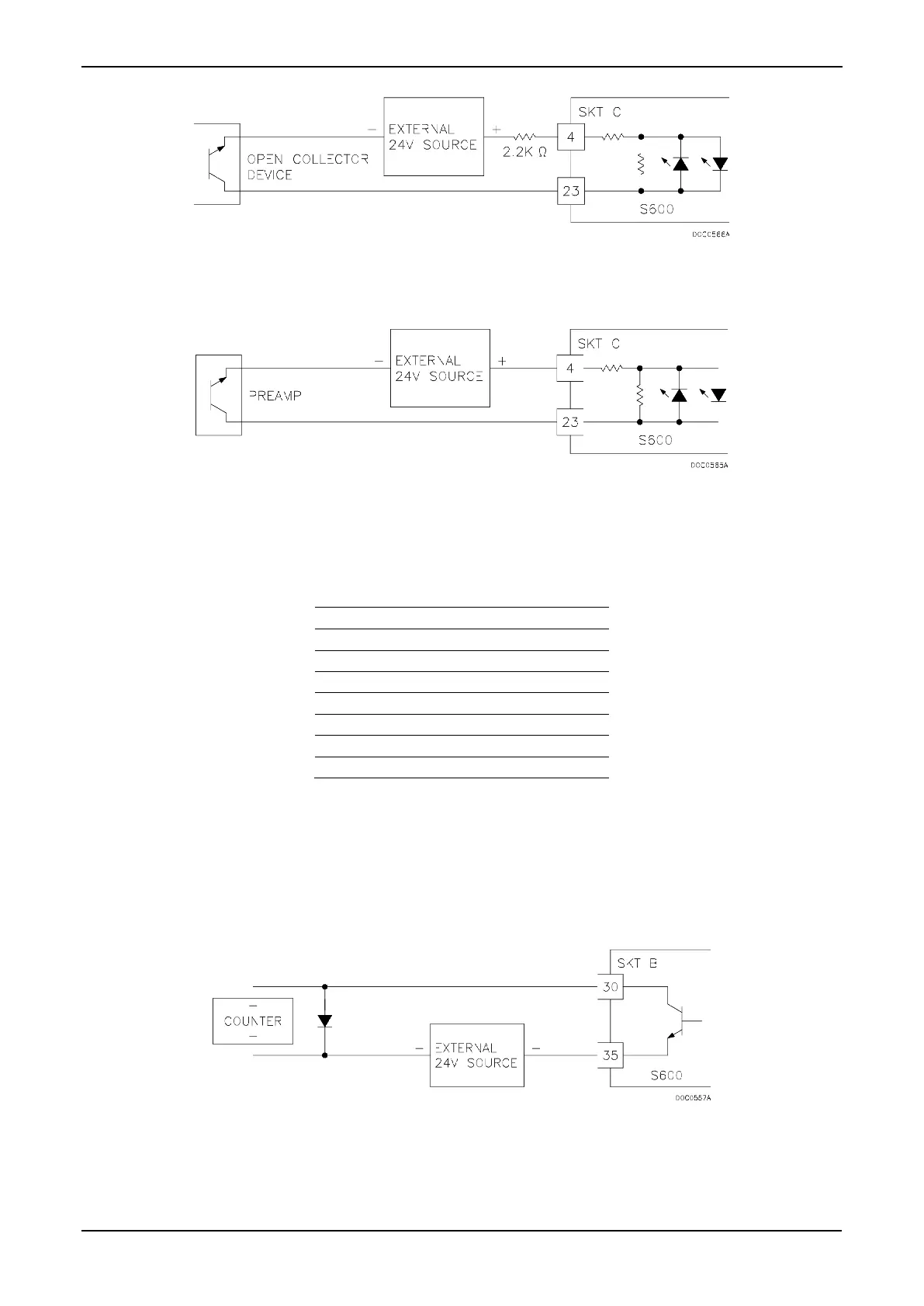
Figure 4-13. Pulse Input Schematic (with 12 V P148 Mezzanine Module)
Figure 4-14. Pulse Input Schematic (with 24 V P148 Mezzanine Module)
Table 4-8. Dual Pulse Input Pin Connections for SKT-C
Pin
Function
4
SINGLE/DUAL PULSE-CH1+
23
SINGLE/DUAL PULSE-CH1-
3
SINGLE/DUAL PULSE-CH2+
22
SINGLE/DUAL PULSE-CH2-
2
SINGLE/DUAL PULSE-CH3+
21
SINGLE/DUAL PULSE-CH3-
1
SINGLE/DUAL PULSE-CH4+
20
SINGLE/DUAL PULSE-CH4-
4.1.6 Pulse Outputs (PULSEOUT)
The system supports five programmable pulse output channels
(PULSEOUT), which are typically used for electronic counters or
sampler control. Refer to Figure 4-15.
Table 4-9 shows the PULSEOUT pin connections.
Figure 4-15. Pulse Output Schematic

Table of Contents

Other manuals for Emerson FloBoss S600+

Questions and Answers:

Question and Answer IconNeed help?

Do you have a question about the Emerson FloBoss S600+ and is the answer not in the manual?

Emerson FloBoss S600+ Specifications

General IconGeneral
BrandEmerson
ModelFloBoss S600+
CategoryController
LanguageEnglish

Related product manuals