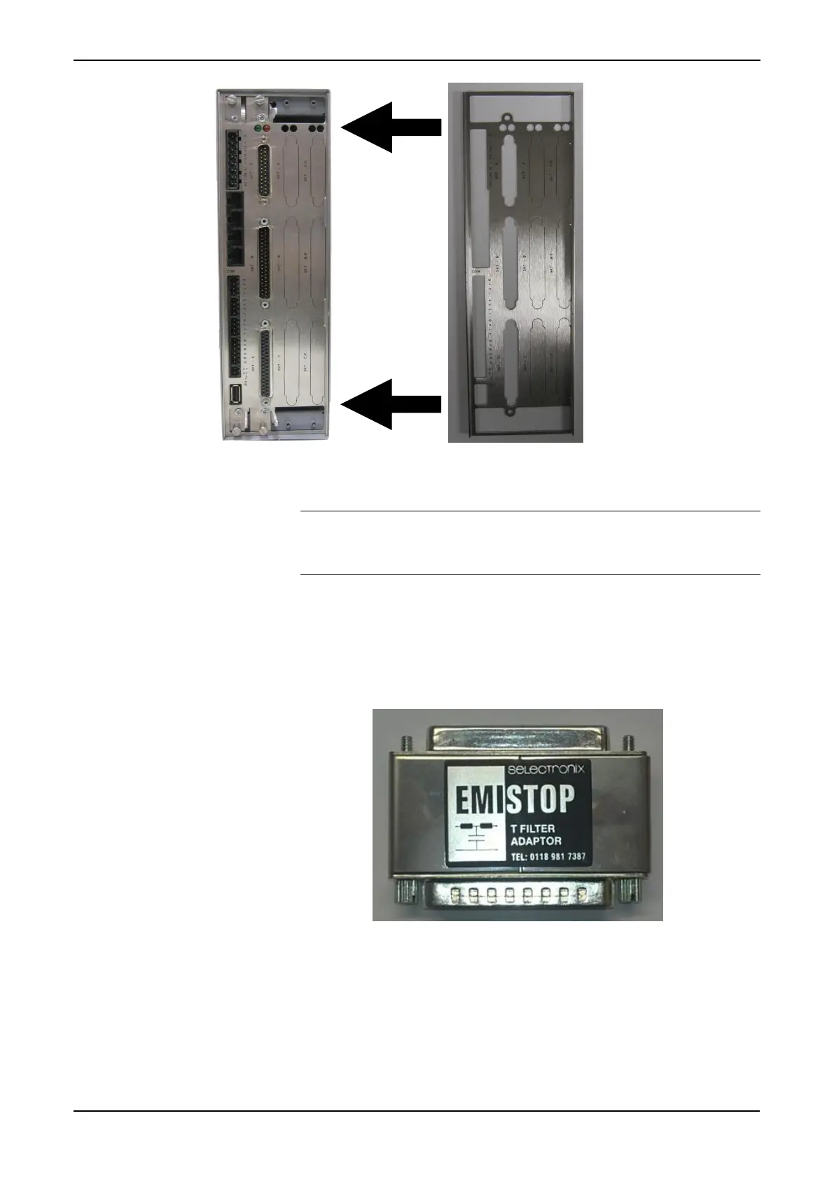
Figure 2-12. Security Backplate in Place
Note: In actual operation, the two right-most slots on the S600+
shown in Figure 2-12 would either contain modules or
would be covered by blanking plates.
3. Secure the backplate to the sides of the S600+ housing using the 2
M3 x 6mm screws.
4. Place and secure the 25-way and 37-way EMISTOP adaptors (see
Figure 2-13) onto, respectively, sockets A and B on the I/O module
(see Figure 2-14).
Figure 2-13. EMISTOP Connector
5. Wire the modules according to your site’s requirements.
6. Attach a small ferrite clamp onto the wiring to socket A on the I/O
module. Attach large ferrite clamps onto the cables to sockets B
and C (see Figure 2-14).