S600+ Instruction Manual
4-4 I/O Revised July-2017
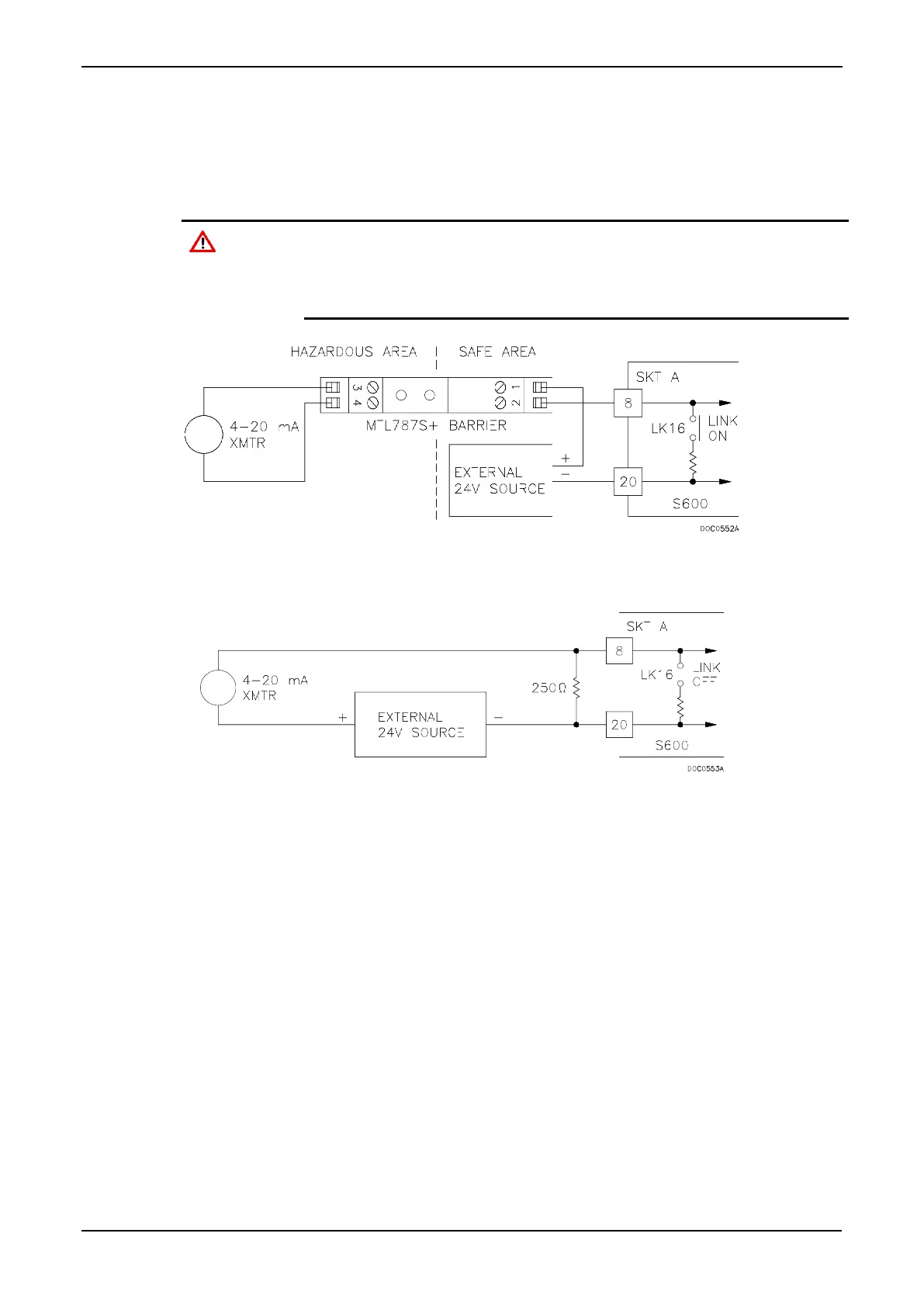
The primary measurement for ANIN 1-10 is voltage, which is
compared to a stable reference source. The channels are configurable
to current using a bit link (jumper) on the module to place a high
accuracy calibrated shunt resistor in parallel with the input. Refer to
Figures 4-4 and 4-5.
Set the channels for each A/D converter to the same value to guarantee
accuracy. Set all channels ANIN 1-5 on the first A/D converter for either
voltage or current. Set all channels ANIN 6-10 on the second A/D
converter for either voltage or current. Refer to Table 4-13 for jumper
settings on the I/O module.
Figure 4-4. Analogue Input Schematic (with IS Barrier and using Internal Resistor)
Figure 4-5. Analogue Input Schematic (without IS Barrier and using External Resistor)
The ANIN channels use the connectors labeled SKT-A and SKT-B,
which are located on the backplate of the I/O module. Channels CH1
to CH10 are located on connector SKT-A. Channels CH11 and CH12
are located on connector SKT-B. Refer to Tables 4-1 and 4-2 for the
ANIN pin connectors.