Epson Artisan 800/Epson Stylus Photo PX800FW/TX800FW/Epson Artisan 700/Epson Stylus Photo PX700W/TX700W
Routing FFC/cables
https://www.manualsbooks.com
Mounted only in Japanese
models.
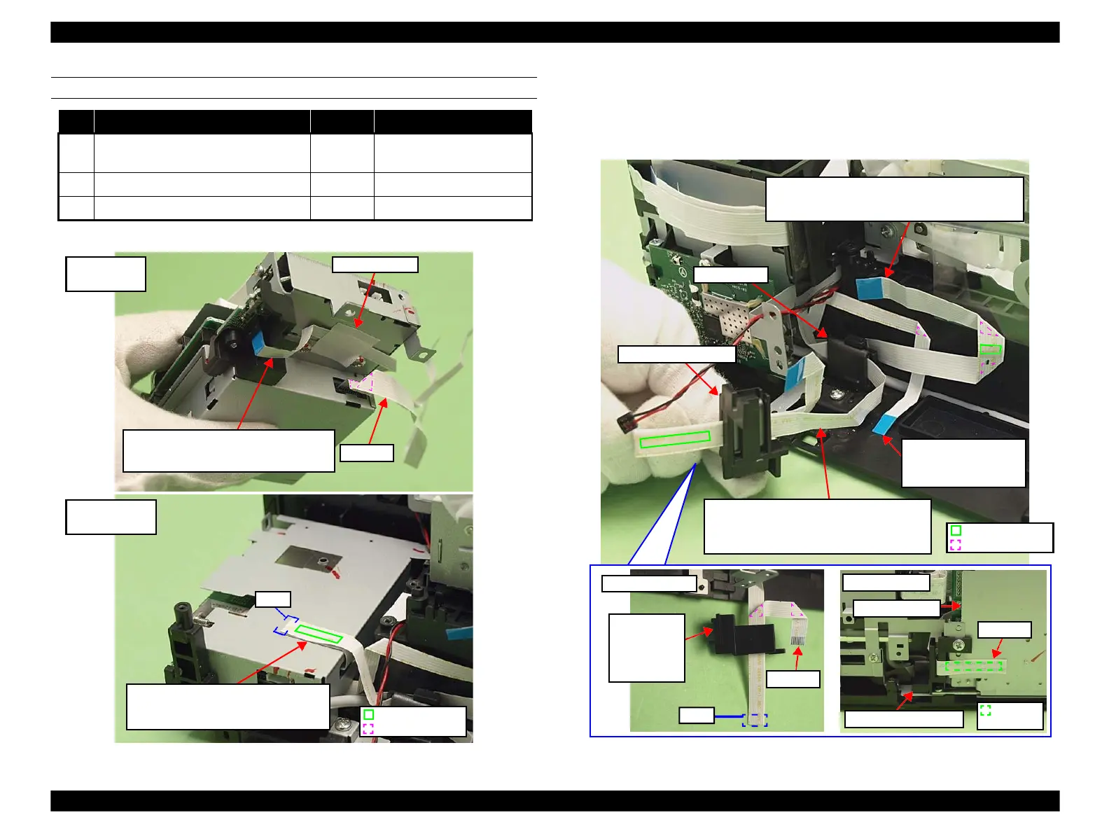
Note * : See Fig. 4-245 for the connector positions on the Main Board.
Figure 4-249. Card Slot Assy (1)
Figure 4-250. Card Slot Assy (2)
Holder A after
folding it back
Double-sided tape
Fold line
STG FFC:
Insert ferrite core on STG FFC into Base Frame,
and put the FFC through Ferrite Core Holder A,
then attach them to the Main Board Unit.
I/F FFC (Mounted only in
Japanese models.):Route
this between SUB FFC
and Base Frame.
SUB FFC:
Route this between Ferrite Core and Base Frame, and
secure it to the Main Board Unit with double-sided tape
Double-sided tape
Fold line
STG FFC:
Fold this back to the front of the Card Slot
Assy and secure it with acetate tape.
Front side of the
Card Slot Assy
I/F FFC (Mounted only in Japanese
models.):Secure this with acetate tape on the
bottom of the Card Slot Assy.
Bottom of the
Card Slot Assy
 Loading...


