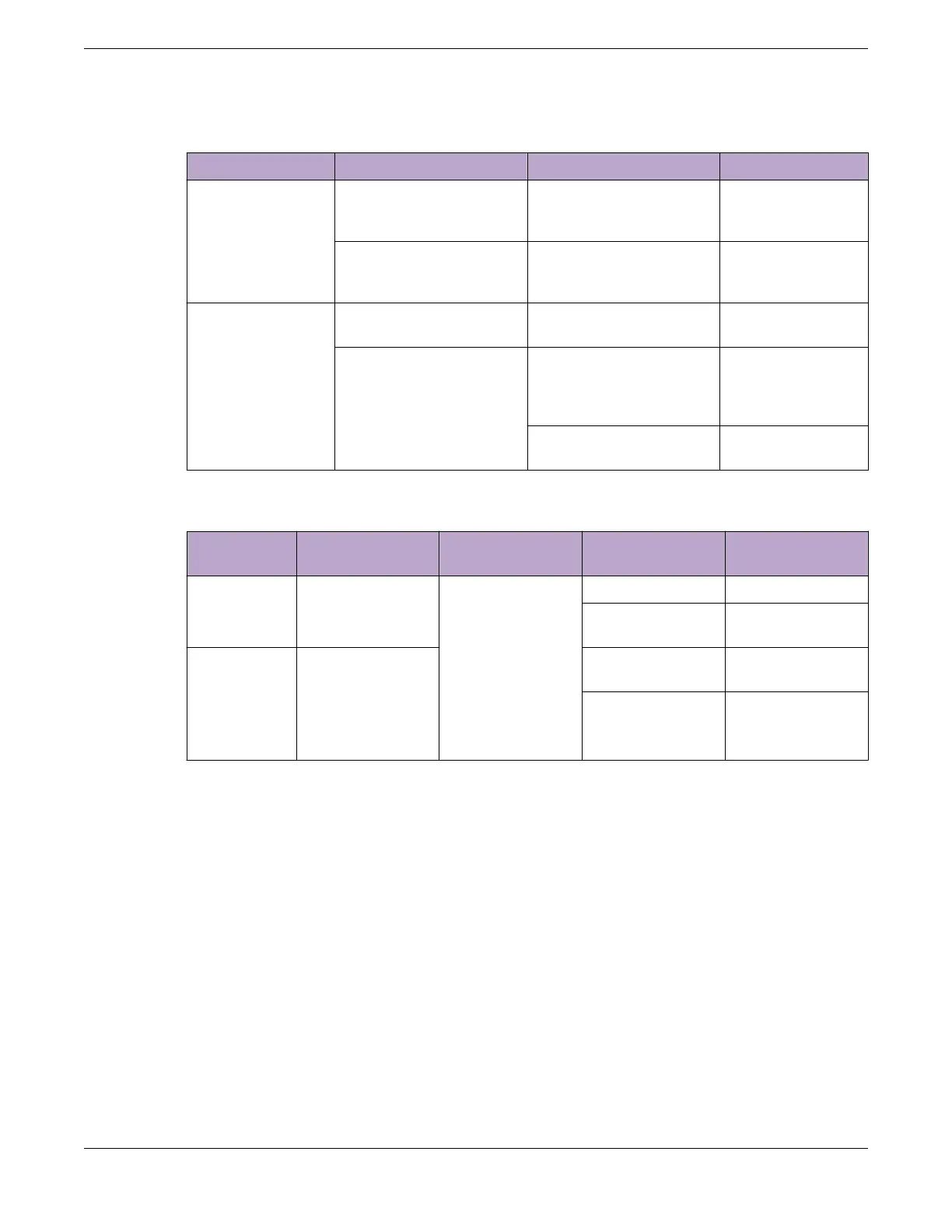
Table 36: X695 System LEDs (continued)
LED indication Color Behavior Description
Fantray 1 (Back)
Fantray 2 (Back)
Fantray 3 (Back)
Fantray 4 (Back)
Fantray 5 (Back)
Fantray 6 (Back)
Green Solid All diagnostics pass
and the module is
operational
Red Solid Failure, module not
receiving power, not
present
FAN
(front faceplate)
Green Solid All modules are
operational
Amber Blinking Failure in at least one
of the modules or
POST in progress if
SYS is solid amber
Solid POST in progress if
SYS is solid amber
The X695 front panel port LEDs behave as follows:
Location Speed LED
Indication
Color/State Description
LED
Port 1-48 (10G
bps)
10G/1Gbps Link/
Act/
Speed
Solid green The port has link
Blinking green Port is transmitting
or receiving
LED Port
49-62.
Ports 49, 50,
55, 60-62 are
not
partitionable
40Gbps/
100Gpbs
(no partition)
Solid green (1)
(2, 3, 4 - O)
The port has link
Blinking green (1)
(2, 3, 4 - O)
Port is transmitting
and/or receiving
ExtremeSwitching Switches ExtremeSwitching X695 Switch LEDs
ExtremeSwitching Hardware Installation Guide 111
 Loading...
