3. Verify that the ground wire is attached to the power supply.
See Figure 193 on page 248.
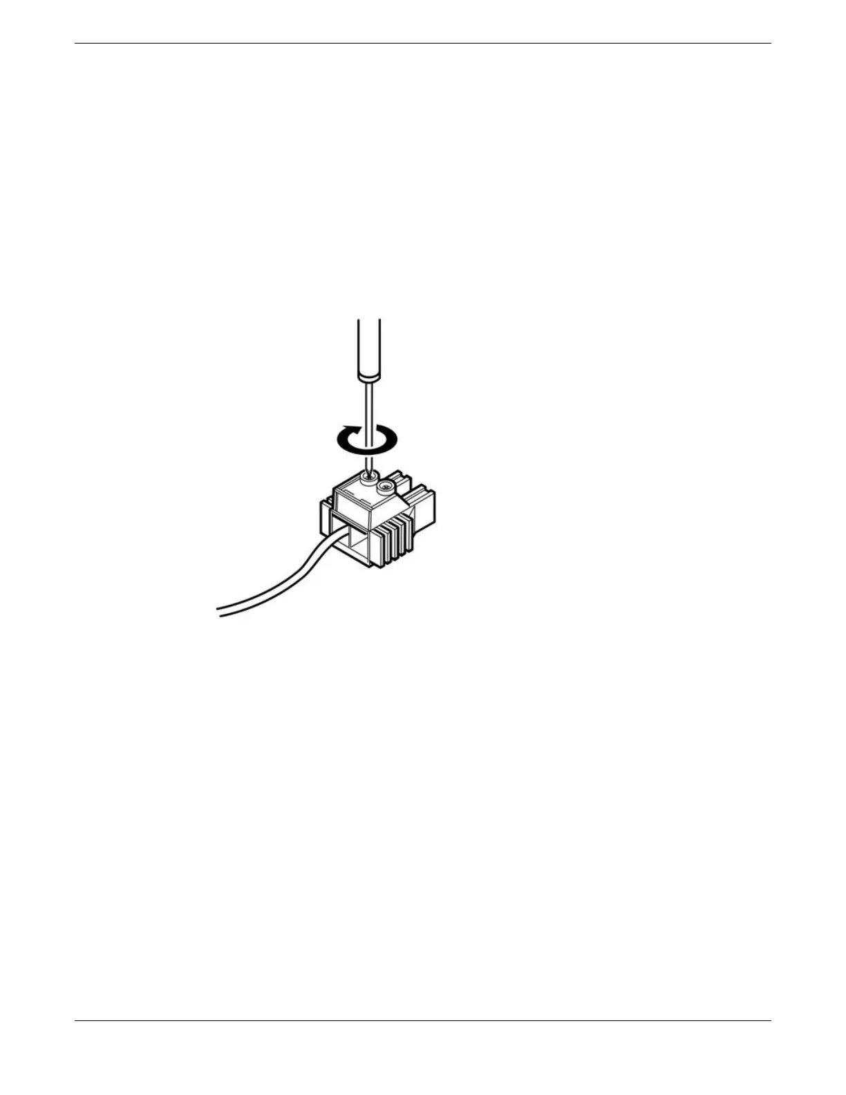
4. Insert a screwdriver into both slots on the top of the terminal connector and loosen the screws
enough to accommodate a stripped power input cable.
5. Insert the DC power cables into the connector.
a. Slide the end of the positive wire (–48 V RTN) into the positive terminal (labeled +, on the left
side of the connector).
b. Tighten the screw on the top of the positive terminal connector to between 4.4 in‑lb (0.50 N m)
and 7.1 in‑lb (0.8 N m).
See Figure 194.
Figure 194: Inserting the DC Power Cables into the Connector
c. Slide the end of the negative wire (–48 V) into the negative terminal (labeled –, on the right side
of the connector).
d. Tighten the screw on the top of the negative terminal connector to between 4.4 in‑lb (0.50 N m)
and 7.1 in‑lb (0.8 N m).
Installing Your Extreme Networks Switch
Install an 1100 W Internal DC Power Supply
ExtremeSwitching Hardware Installation Guide 249
 Loading...
