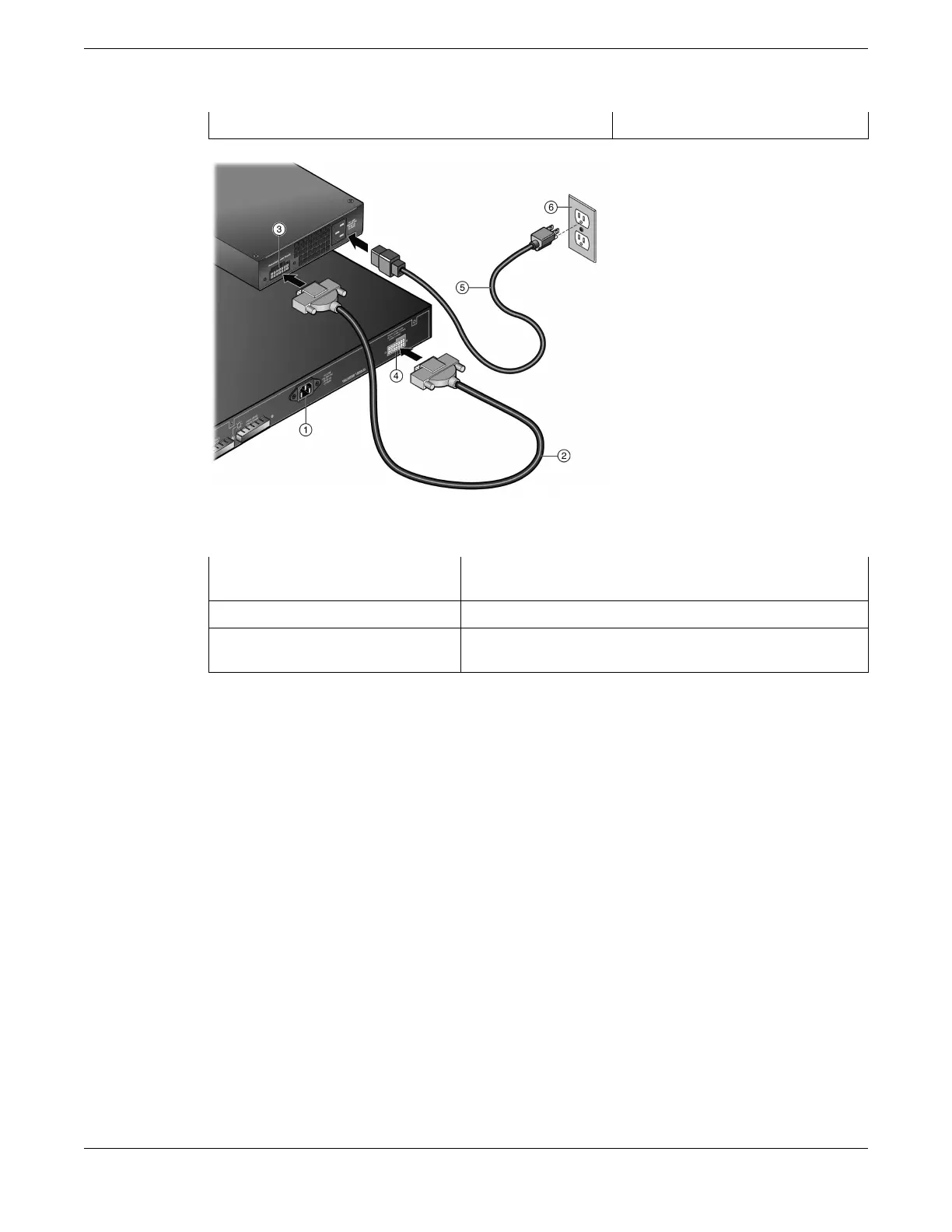
1 = Redundant power supply connector 2 = AC power connector
Figure 227: RPS and AC Power Cord Connections
1 = Switch
4 = Switch Redundant Power Supply connector (location varies
depending upon switch)
2 = High speed RPS cable (1 meter) 5 = AC power cord (type varies depending on country)
3 = RPS Redundant Power Supply
connector
6 = AC power outlet with ground connection (type varies
depending on country)
2. Connect the AC power cord to the AC input power connector on the RPS shown in the figure above.
3. Plug the AC power cord into the main AC power outlet.
The green Power LED on the front of the RPS will illuminate to indicate a successful connection. On
certain switches, an LED indicator on the switch will show that a redundant power supply is now in
operation.
If the green power LED is not lit, proceed as follows:
• Check the AC power cord connection at the AC power source and make sure the power source is
within
specification.
• Check the AC power connection to the power supply.
• Swap the AC power cord with one that is known to work properly.
If the green LED remains o, contact Extreme Networks support.
Installing External Power Supplies
Connecting the RPS Cable and AC Power Cord
ExtremeSwitching Hardware Installation Guide 285
 Loading...
