c. Slide the end of the negative wire (–48 V) into the negative terminal (labeled –, on the right side
of the connector).
d. Tighten the screw on the top of the negative terminal connector to between 4.4 in‑lb (0.50 N m)
and 7.1 in‑lb (0.8 N m).
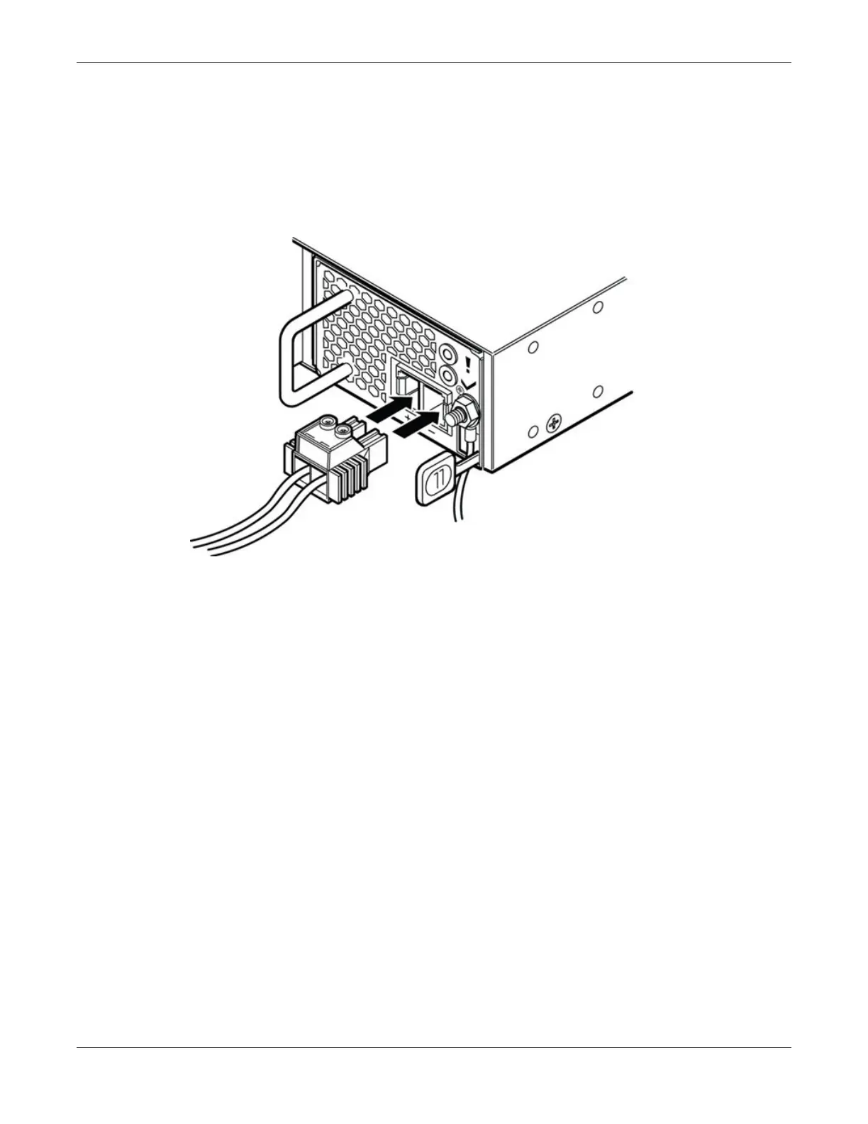
6. Insert the connector into the slot on the power supply.
See Figure 307.
Figure 307: Inserting the Connector into the Power Supply
7. Connect the cables to the DC source voltage, using hardware appropriate to the installation site and
following local and national electrical codes.
8. Energize the DC circuit.
Replacing DC Power Supplies
Connect DC Power Cables to an 1100 W DC Power
Supply
ExtremeSwitching Hardware Installation Guide 367
 Loading...
