Operating Procedures: Patterning
C O N F I D E N T I A L – FEI Limited Rights Data5-56
Milling in Spot Mode
This procedure is convenient to drill holes with diameter
depending on the beam size.
1. Select the Scan menu / Spot mode. In this mode no scanning
takes place.
The single spot (green cross) cursor appears directly in the
center of the screen. If the cursor is not moved the milling
process will take place here otherwise click anywhere on the
image to move the spot to another position.
2. Move the feature to be drilled to the green cross cursor.
3. Start the beam.
4. To acquire an image, click on the Snapshot button.
5. Release (unpause) active display to proceed with milling.
6. To exit spot mode, select the Scan menu / Full Frame item.
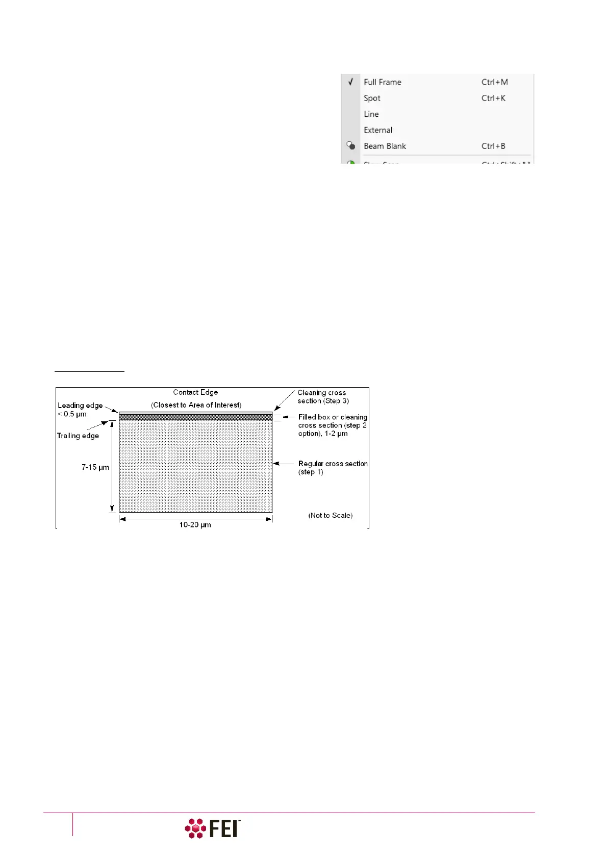
Creating Cross Sections
Cross sections are cut in a stair step way to allow the exposed layers to be seen with the electron beam when the
stage is tilted to 52°. Typically this process runs in two or three stages.
• The first stage is to mill a Regular Cross Section with five superimposed box patterns sharing common edges.
• For the second (optional) stage use either pattern type with Property tab module / Fill Style set to Solid or the
Cleaning cross section at a reduced current. (If the cross section is large, the second cleaning may be required at a
lower current.)
• For the third stage, use the Cleaning Cross Section.
The following figure shows the relation of these pattern areas and their relative sizes.
FIGURE 5-14 Typical Cross Section
A typical cross section is 10–20 µm wide by 7–15 µm high with the dimensions and depth appropriate to the size of
the target area of interest.
Use caution in positioning boxes if you are sectioning a very specific point. Use fine milling to expose the exact area
of interest. For example, 2 µm offset should be enough at 2 nA beam current.
Calculate the outline as the height of the box relative to the depth to be milled. If you intend to view at 52° and see
details 3 µm from the surface, then the original box should be at least 3 µm high.