G.3.3.15 Trigger Level, +8Vdc
This screen displays:
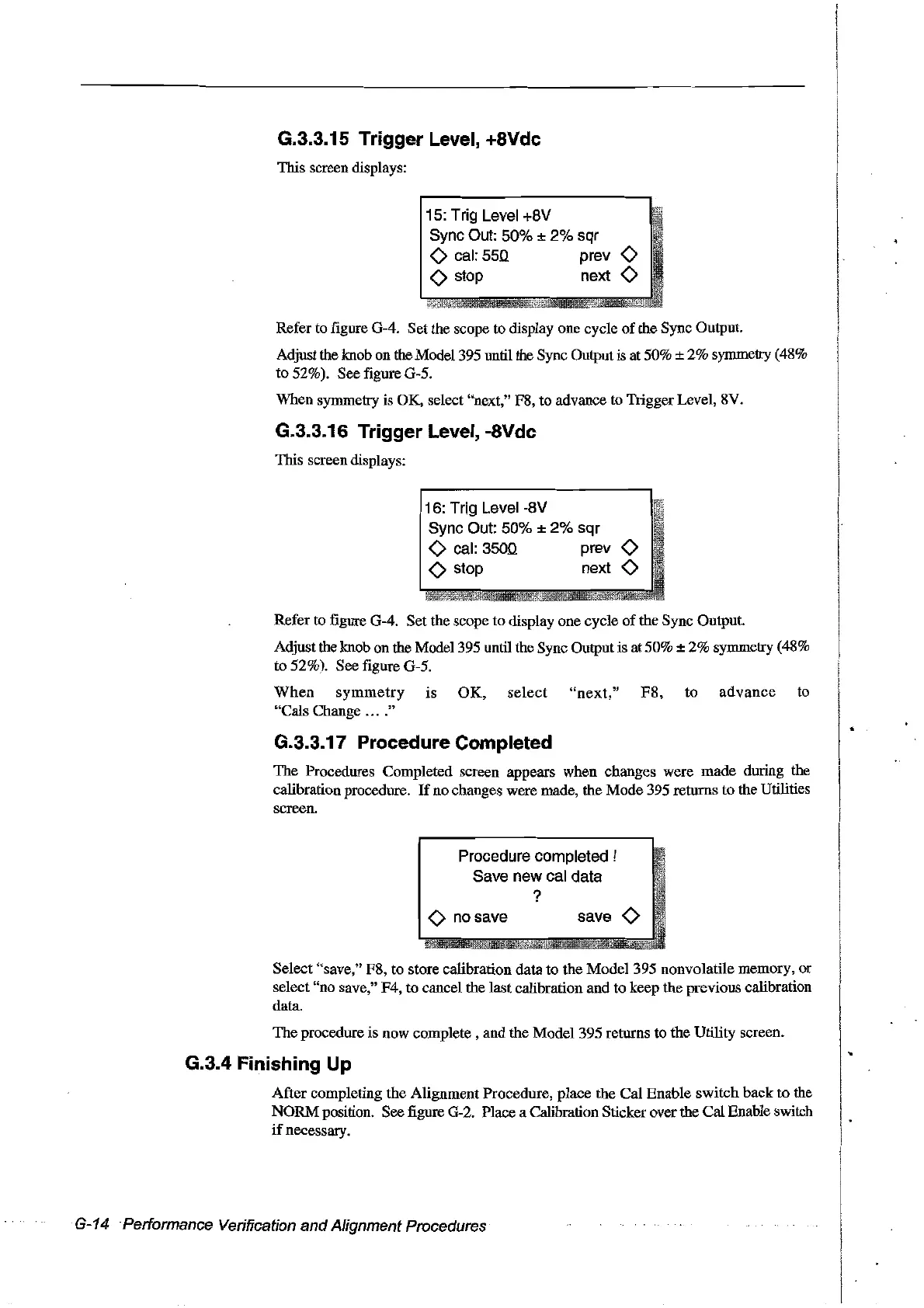
15: Trig Leve1+8V
Sync Out: 50%
±
2%
sqr
<>
cal:
550
prev
<>
<>
stop next
<>
Refer to figure G-4. Set the scope to display one cycle
of
the Sync Output.
Adjust the knob on the Model395 until the Sync Output
is at 50% ± 2% symmetry (48%
to 52%). See figure G-5.
When symmetry is OK, select "next," F8, to advance to Trigger Level, 8V.
G.3.3.16 Trigger Level, -8Vdc
This screen displays:
16: Trjg Level -8V
Sync Out: 50%
±
2%
sqr
<>
cal:
3500
prev
<>
<>
stop next
<>
Refer to figure G-4. Setthe scope to display one cycle
of
the Sync Output.
Adjust the knob on the Model 395 until the Sync Output
is
at 50% ± 2% symmetry (48%
to 52%). See figure G-5.
When
symmetry
IS
OK,
select
"next,"
F8,
to
advance
to
"Cals Change
...
."
G.3.3.17 Procedure Completed
The Procedures Completed screen appears when changes were made during the
calibration procedure.
If
no changes were made, the Mode 395 returns to the Utilities
screen.
Procedure completed !
Save new cal data
?
<>
no save
save
<>
Select "save," F8, to store calibration data to the Model 395 nonvolatile memory, or
select "no save," F4, to cancel the last calibration and to keep the previous calibration
data.
The procedure is now complete, and the Model 395 returns to the Utility screen.
G.3.4 Finishing Up
After completing the Alignment Procedure, place the Cal Enable switch back to the
NORM position. See figure G-2. Place a Calibration Sticker over the Cal Enable switch
if
necessary.
G-14 Performance Verification
and
Alignment Procedures
Artisan Technology Group - Quality Instrumentation ... Guaranteed | (888) 88-SOURCE | www.artisantg.com