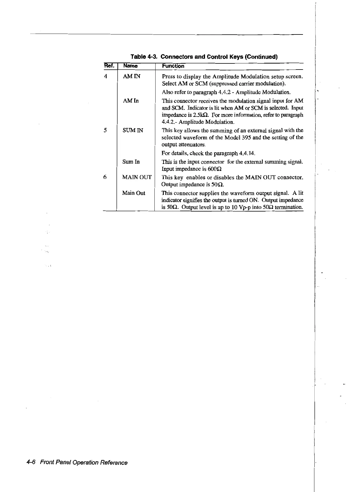
Table 4-3. Connectors and Control Keys (Continued)
Ret. Name Function
4
5
6
AM IN Press to display the Amplitude Modulation setup screen.
Select
AM
or SCM (suppressed carrier modulation).
AIso refer to paragraph 4.4.2 - Amplitude Modulation.
AM
In
This connector receives the modulation signal input for
AM
and SCM. Indicator
is
lit when AM or SCM is selected. Input
impedance
is
2.5kQ. For more information, refer
to
paragraph
4.4.2.- Amplitude Modulation.
SUM IN This key allows the summing
of
an external signal with the
selected waveform of the Model 395 and the setting
of
the
output attenuators.
For details, check the paragraph 4.4.14.
Sum In This is the input connector for the external summing signal.
Inputimpedanceis600r!
MAIN OUT This key enables or disables the MAIN OUT connector.
Output impedance is
50n.
Main Out This connector supplies the waveform output signal. A lit
indicator signifies the output is turned
ON.
Output impedance
is 50r!. Output level is up to
10
Vp-p into
50n
terillÎnation.
4-6 Front Panel Operation Reference
Artisan Technology Group - Quality Instrumentation ... Guaranteed | (888) 88-SOURCE | www.artisantg.com