Vp
<>
dBm
<>
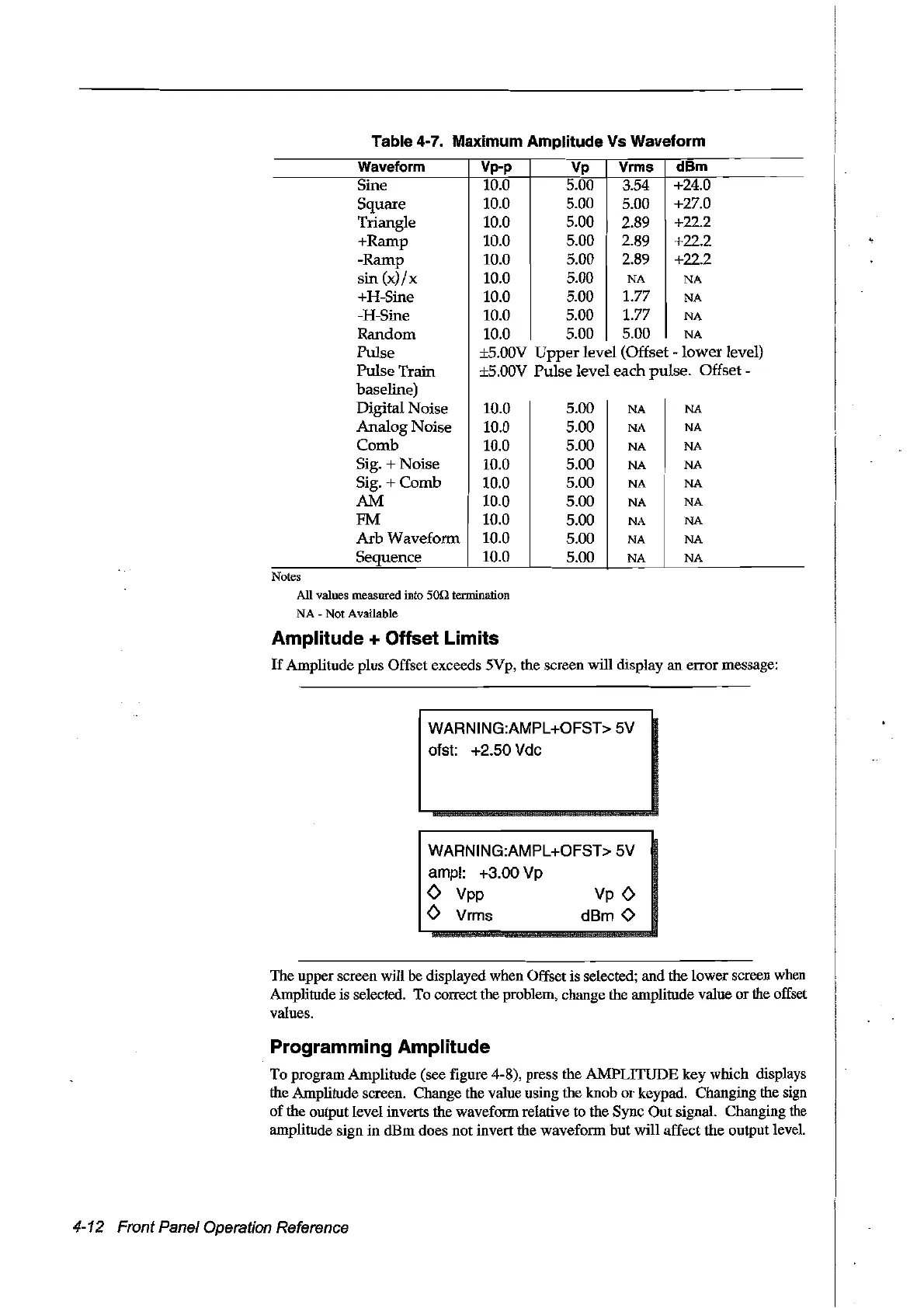
Table 4-7. Maximum Amplitude Vs Waveform
Waveform
Vp-p
Vp Vrms
dBm
Sine
10.0 5.00
354
+24.0
Square
10.0 5.00 5.00
+27.0
Triangle 10.0
5.00 2.89 +22.2
+Ramp 10.0
5.00 2.89 +22.2
-Ramp
10.0 5.00 2.89 +22.2
sin
(x)/x
10.0 5.00
NA
NA
+H-Sine 10.0 5.00 1.77
NA
-H-Sine
10.0 5.00
1.77
NA
Random
10.0 5.00
5.00
NA
Pulse
±S.OOV
Upper
level (Offset
-lower
level)
Pulse Train ±5.00V Pulse level each pulse.
Offset-
baseline)
Digital Noise 10.0 5.00
NA
NA
Analog Noise 10.0 5.00
NA
NA
Comb 10.0
5.00
NA NA
Sig. + Noise
10.0
5.00
NA NA
Sig. + Comb 10.0 5.00
NA
NA
AM
10.0 5.00
NA
NA
FM 10.0 5.00
NA
NA
Arb
Waveform 10.0 5.00
NA NA
Sequence
10.0
5.00
NA
NA
Notes
AU
values measured into 50n termination
NA
- Not Available
Amplitude + Offset Limits
If
Amplitude plus Offset exceeds 5Vp, the screen will display an errormessage:
WARNING:AMPL+OFST>
SV
ofst: +2.S0 Vdc
WARNING:AMPL+OFST> SV
ampl: +3.00 Vp
<>
Vpp
<>
Vrms
The upper screen will be displayed when Offset is selected; and the lowerscreen when
Amplitude is selected. To correct the problem, change the amplitude value
or
the offset
values.
Programming Amplitude
To program Amplitude (see figure 4-8), press the AMPLITUDE key which displays
the Amplitude screen. Change the value using the knob
or
keypad. Changing the sign
of
the output level inverts the waveform relative
to
the Sync Out signal. Changing
the
amplitude sign
in
dBm
does not invert the waveform
but
will affect the output level.
4-12 Front Panel Operation Reference
Artisan Technology Group - Quality Instrumentation ... Guaranteed | (888) 88-SOURCE | www.artisantg.com