MB95630H Series
MN702-00009-2v0-E FUJITSU SEMICONDUCTOR LIMITED 147
CHAPTER 11 8/16-BIT COMPOSITE TIMER
11.7 Operation of Interval Timer Function
(Continuous Mode)
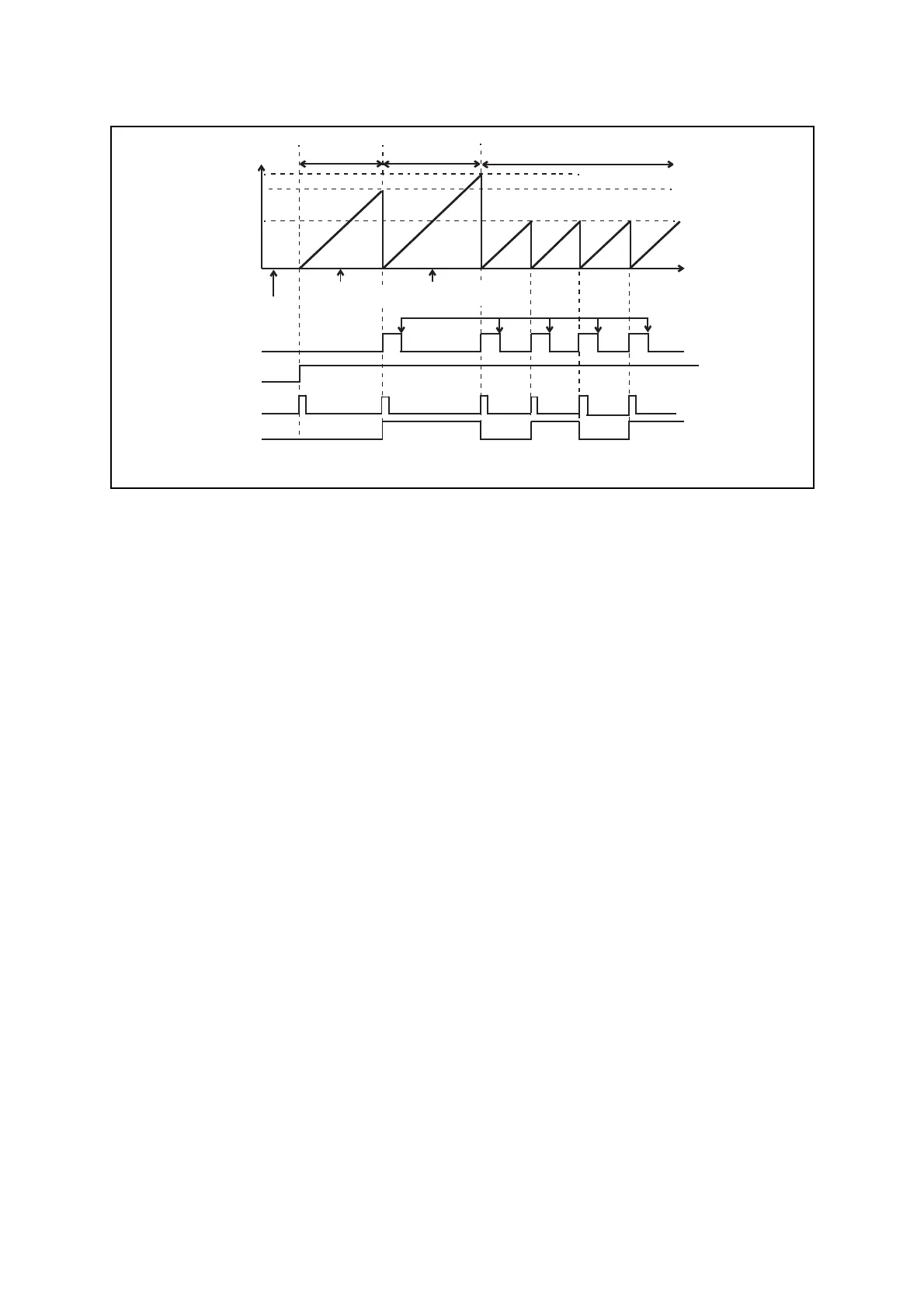
Figure 11.7-2 Operation Diagram of Interval Timer Function (Continuous Mode)
Compare value
Compare value
(0xFF)
Compare value
(0x80)
0xFF
0x80
0x00
Tn0DR/Tn1DR value (0xE0)
Cleared by program
Time
IF bit
STA bit
Counter clear
*2
Timer output pin
*1: If the Tn0DR/Tn1DR data register value is modified during operation, the new value is used from the next active cycle.
0xE0
Compare value
(0xE0)
Activated Matched Matched Matched Matched Matched
*2: The counter is cleared and the data register settings are loaded into the comparison data latch whenever a match is detected during operation.
Tn0DR/Tn1DR value
modified (0xFF→0x80)
*1
Tn0DR/Tn1DR
value modified
(0xE0→0xFF)
*1