MB95630H Series
586 FUJITSU SEMICONDUCTOR LIMITED MN702-00009-2v0-E
CHAPTER 27 NON-VOLATILE REGISTER (NVR) INTERFACE
27.3 Registers
27.3.2 Main CR Clock Trimming Register (Lower) (CRTL)
This section describes the main CR clock trimming register (lower) (CRTL).
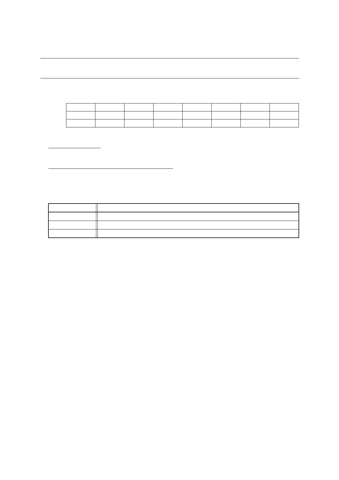
■ Register Configuration
■ Register Functions
[bit7:5] Undefined bits
Their read values are always "0". Writing values to these bits has no effect on operation.
[bit4:0] CRTL[4:0]: Main CR clock fine trimming bits
The settings of these bits are loaded from the Flash address 0xFFBD (bit4:0) after a reset. Their initial values
are determined by the pre-loaded values in the NVR Flash area.
Fine trimming modifies the main CR clock frequency with a smaller step. Increasing the fine trimming value
decreases the main CR clock frequency.
See "27.4 Notes on Main CR Clock Trimming" and "27.5 Notes on Using NVR Interface" for details of
main CR clock trimming and notes on changing the main CR clock values respectively.
bit 7 6 5 4 3 2 1 0
Field — — — CRTL4 CRTL3 CRTL2 CRTL1 CRTL0
Attribute — — — R/W R/W R/W R/W R/W
Initial value 0 0 0 X X X X X
bit4:0 Details
Writing "00000" Highest main CR clock frequency
: :
Writing "11111" Lowest main CR clock frequency