MB95630H Series
462 FUJITSU SEMICONDUCTOR LIMITED MN702-00009-2v0-E
CHAPTER 22 UART/SIO
22.6 Operations and Setting Procedure Example
22.6 Operations and Setting Procedure Example
The UART/SIO has a serial communication function (operation mode 0, 1).
■ Operations of UART/SIO
● Operation mode
Two operation modes are available in the UART/SIO. Clock synchronous mode (SIO) or clock
asynchronous mode (UART) can be selected (See Table 22.6-1).
■ Setting Procedure Example
Below is an example of procedure for setting the UART/SIO.
● Initial setup
1. Set the port input. (DDR)
2. Set the interrupt level. (ILR*)
3. Set the prescaler. (PSSRn)
4. Set the baud rate. (BRSRn)
5. Select the clock. (SMC1n:CKS)
6. Set the operation mode. (SMC1n:MD)
7. Enable/disable the serial clock output. (SMC2n:SCKE)
8. Enable reception. (SMC2n:RXE = 1)
9. Enable interrupts. (SMC2n:RIE = 1)
*: For details of the interrupt level setting register (ILR), refer to "CHAPTER 5 INTERRUPTS" in this
hardware manual and "■ INTERRUPT SOURCE TABLE" in the device data sheet.
● Interrupt processing
Read receive data. (RDRn)
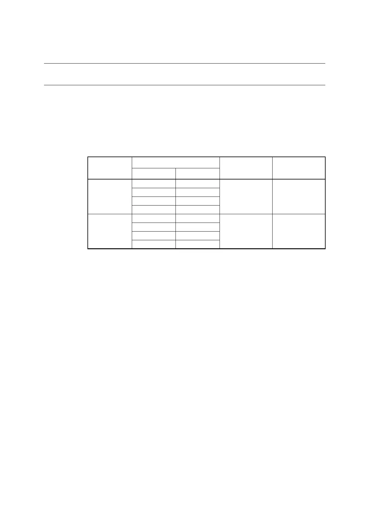
Table 22.6-1 Operation Modes of UART/SIO
Operation mode
Data length
Synchronization
mode
Length of stop bit
No parity With parity
0
56
Asynchronous 1 bit or 2 bits
67
78
89
1
5-
Synchronous -
6-
7-
8-