MB95630H Series
56 FUJITSU SEMICONDUCTOR LIMITED MN702-00009-2v0-E
CHAPTER 3 CLOCK CONTROLLER
3.8 Configuration of Prescaler
3.8 Configuration of Prescaler
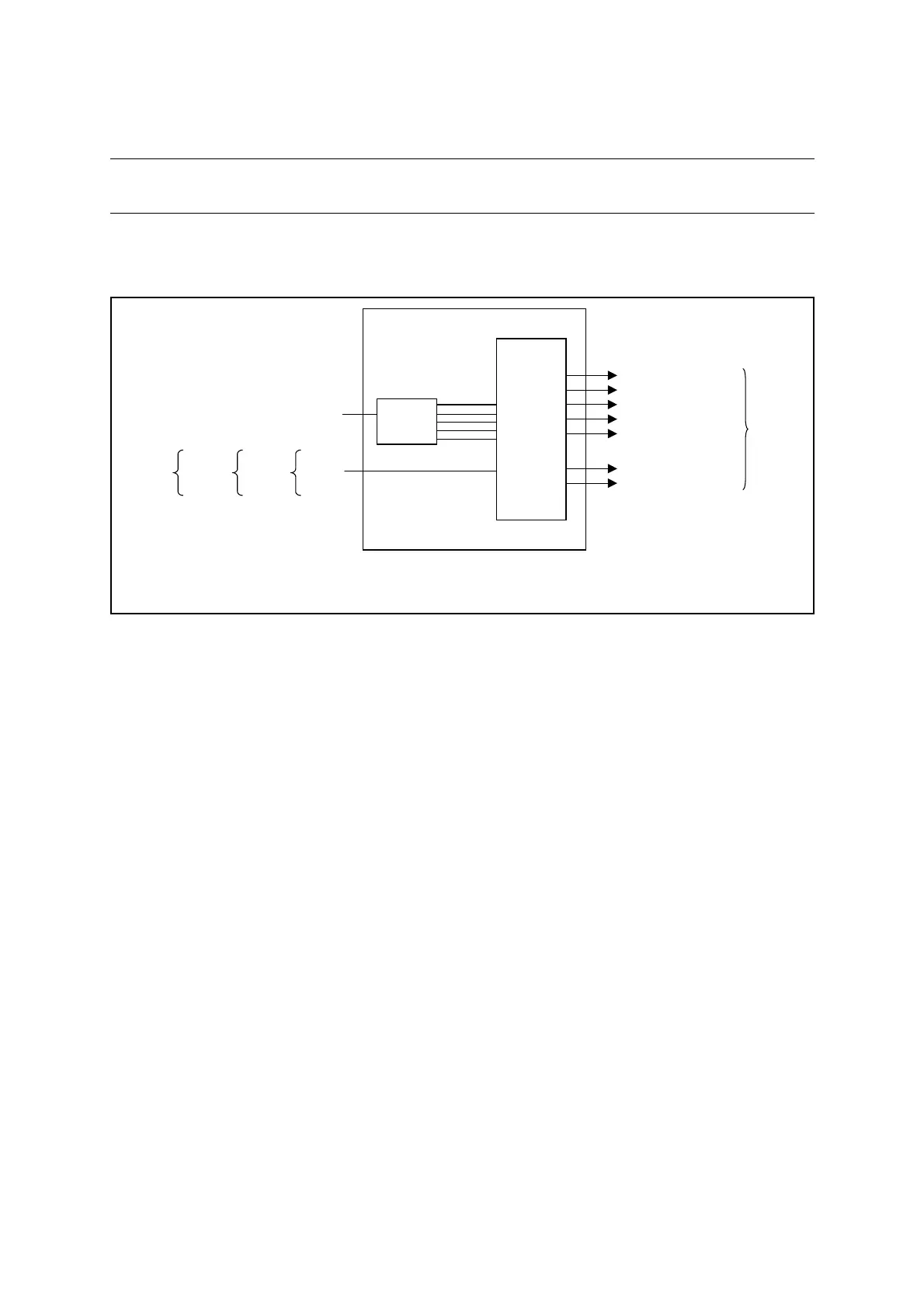
Figure 3.8-1 is the block diagram of the prescaler.
■ Block Diagram of Prescaler
Figure 3.8-1 Block Diagram of Prescaler
• 5-bit counter
This counter counts the machine clock (MCLK) and outputs the count value to the output
control circuit.
• Output control circuit
Based on the 5-bit counter value, this circuit supplies clocks generated by dividing the
machine clock (MCLK) by 2, 4, 8, 16, or 32 to individual peripheral functions. The circuit
also buffers the clock from the time-base timer (F
CH
/2
7
, F
CH
/2
8
, F
CRH
/2
6
, F
CRH
/2
7
,
F
MCRPLL
/2
6
, or
F
MCRPLL
/2
7
) and supplies it to peripheral functions.
■ Input Clock
The prescaler uses the machine clock, or the output clock of the time-base timer as the input
clock.
■ Output Clock
The prescaler supplies clocks to the following peripheral functions:
• 8/16-bit composite timer
• 8/10-bit A/D converter
• 8/16-bit PPG
• 16-bit PPG timer
• 16-bit reload timer
• UART/SIO dedicated baud rate generator
MCLK
F
CH
FCRH
FMCRPLL
: Machine clock (internal operating frequency)
: Main clock frequency
: Main CR clock frequency
: Main CR PLL clock frequency
Prescaler
Output
control circuit
MCLK (machine clock)
Count
clock
source
to
different
peripheral
functions
5-bit
counter
FCH/2
7
, FCRH/2
6
or FMCRPLL/2
6
MCLK/2
FCH/2
8
, FCRH/2
7
or FMCRPLL/2
7
MCLK/4
MCLK/8
MCLK/16
MCLK/32
Counter value
FMCRPLL/2
6
FMCRPLL/2
7
or
F
CH/2
7
FCH/2
8
From
time-base
timer
FCRH/2
6
FCRH/2
7
or