MB95630H Series
MN702-00009-2v0-E FUJITSU SEMICONDUCTOR LIMITED 221
CHAPTER 14 LIN-UART
14.6 Operations of LIN-UART and LIN-UART
Setting Procedure Example
14.6 Operations of LIN-UART and LIN-UART Setting
Procedure Example
The LIN-UART performs bi-directional serial communication in operating mode
0/2, master/slave communication in operating mode 1, LIN master/slave
communication in operating mode 3.
■ Operations of LIN-UART
● Operating mode
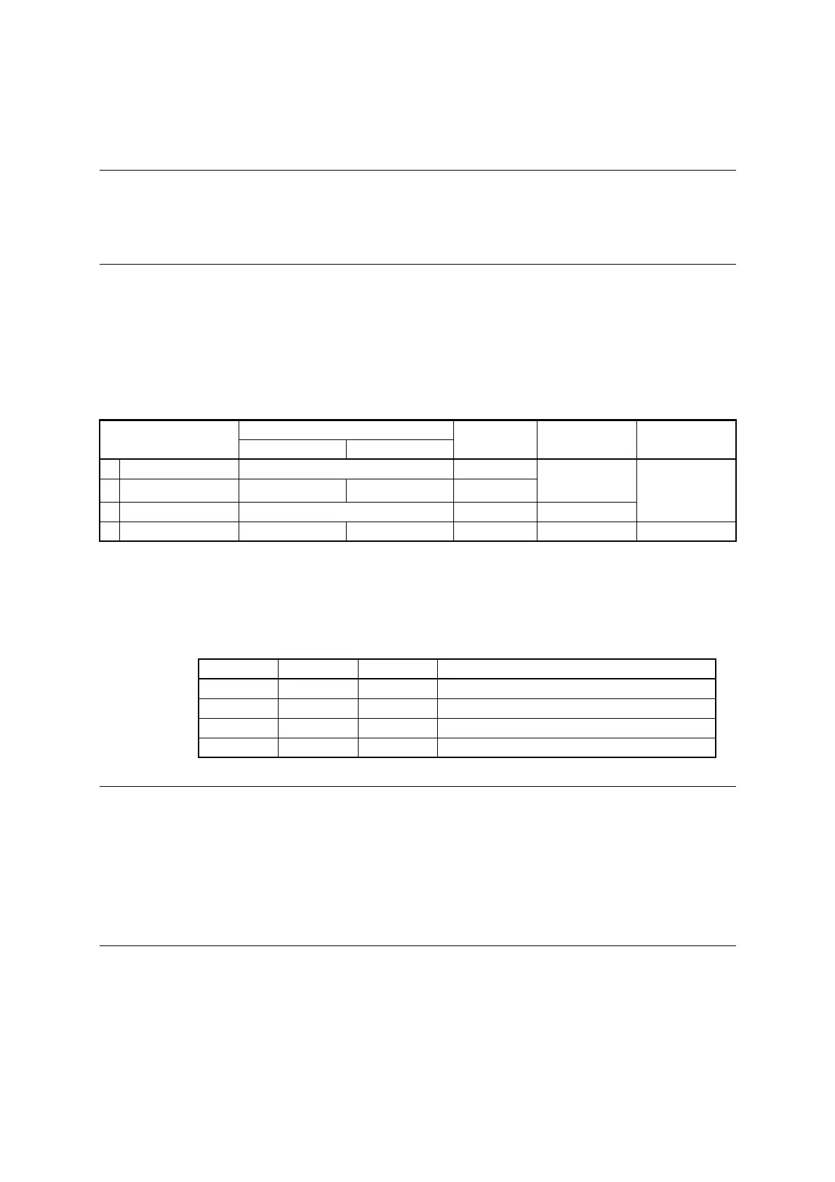
The LIN-UART has four operating modes (0 to 3), providing different connection methods
between CPUs and different data transfer methods as shown in Table 14.6-1.
The MD0 and MD1 bits in the LIN-UART serial mode register (SMR) are used to select the
following LIN-UART operating modes.
Notes:
• In operating mode 1, a system connecting to a master/slave supports both master
operations and slave operations.
• In operating mode 3, the communication format is fixed at "8-bit data, no parity bit, one
stop bit, LSB-first".
• If the operating mode is changed, all transmission operations and reception operations
are canceled, and the LIN-UART waits for the next transmission/reception.
Table 14.6-1 LIN-UART Operating Modes
Operating mode
Data length
Synchronous
method
Stop bit length Data bit format
No parity With parity
0 Normal mode 7 bits or 8 bits Asynchronous
1 bit or 2 bits
LSB first
MSB first
1 Multiprocessor mode
7 bits or 8 bits +1
*
- Asynchronous
2 Normal mode 8 bits Synchronous None, 1 bit, 2 bits
3 LIN mode 8 bits - Asynchronous 1 bit LSB first
-: Unavailable
*: "+1" is the address/data select bit (AD) used for communication control in multiprocessor mode.
Table 14.6-2 LIN-UART Operating Modes
MD1 MD0 Mode Type
0 0 0 Asynchronous (Normal mode)
0 1 1 Asynchronous (Multiprocessor mode)
1 0 2 Synchronous (Normal mode)
1 1 3 Asynchronous (LIN mode)