MB95630H Series
244 FUJITSU SEMICONDUCTOR LIMITED MN702-00009-2v0-E
CHAPTER 14 LIN-UART
14.7 Registers
14.7.1 LIN-UART Serial Control Register (SCR)
The LIN-UART serial control register (SCR) is used to set parity, select the stop
bit length and data length, select the frame data format in operating mode 1,
clear the receive error flag, and enable/disable transmission/reception.
■ Register Configuration
■ Register Functions
[bit7] PEN: Parity enable bit
This bit specifies whether or not to add (at transmission) and detect (at reception) a parity bit.
Note: The parity bit is added only in operating mode 0, or in operating mode 2 in which the start/stop bits
are to be added to the synchronous data format (ECCR:SSM = 1). This bit is fixed at "0" in operating
mode 3 (LIN).
[bit6] P: Parity select bit
With the parity bit having been enabled (SCR:PEN = 1), setting this bit to "1" selects the odd parity and
setting this bit to "0" selects the even parity.
[bit5] SBL: Stop bit length select bit
This bit sets the bit length of the stop bit (frame end mark in transmit data) in operating mode 0, 1
(asynchronous) or in operating mode 2 (synchronous) in which the start/stop bits are to be added to the
synchronous data format (ECCR:SSM = 1).
This bit is fixed at "0" in operating mode 3 (LIN).
Note: At reception, only a framing error for the bit length of the stop bit is always detected.
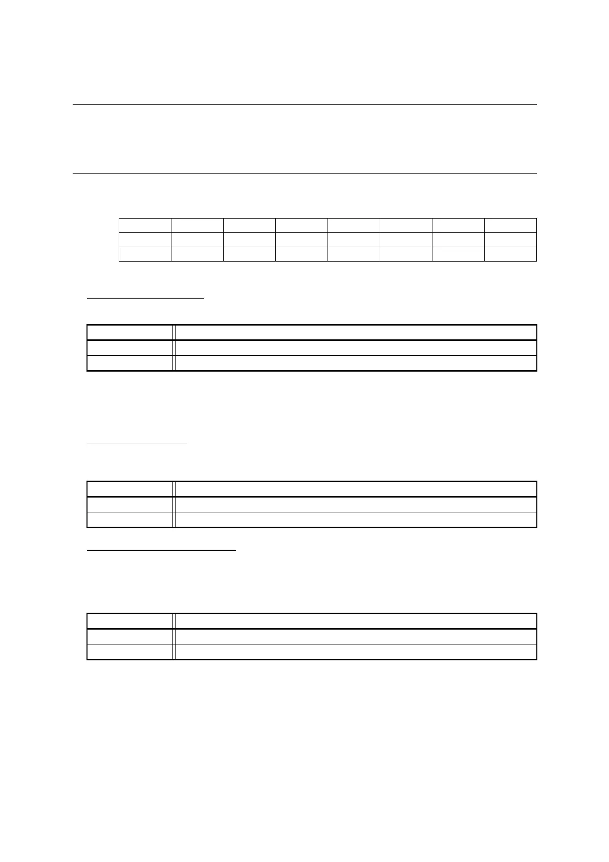
bit 7 6 5 4 3 2 1 0
Field PEN P SBL CL AD CRE RXE TXE
Attribute R/W R/W R/W R/W R/W R/W R/W R/W
Initial value 0 0 0 0 0 0 0 0
bit7 Details
Writing "0" Disables parity.
Writing "1" Enables parity.
bit6 Details
Writing "0" Even parity
Writing "1" Odd parity
bit5 Details
Writing "0" 1 bit
Writing "1" 2 bits