MB95630H Series
170 FUJITSU SEMICONDUCTOR LIMITED MN702-00009-2v0-E
CHAPTER 11 8/16-BIT COMPOSITE TIMER
11.14 Registers
11.14.4 8/16-bit Composite Timer Data Register
(Tn0DR/Tn1DR)
The 8/16-bit composite timer data register (Tn0DR/Tn1DR) is used to set the
maximum count value during the interval timer operation or the PWM timer
operation and to read the count value during the PWC timer operation or the
input capture operation. The Tn0DR and Tn1DR registers correspond to timers
n0 and n1 respectively.
■ Register Configuration
● Interval timer function
The 8/16-bit composite timer data register (Tn0DR/Tn1DR) is used to set the interval time.
When the timer starts operating (Tn0CR1/Tn1CR1:STA = 1), the value of this register is
transferred to the latch in the 8-bit comparator and the counter starts counting. When the count
value matches the value held in the latch in the 8-bit comparator, the value of this register is
transferred again to the latch, and the counter returns to "0x00" and continues to count.
The current count value can be read from this register.
An attempt to write "0x00" to this register is disabled in interval timer function.
In 16-bit operation, write the upper timer data to Tn1DR and lower timer data to Tn0DR, and
write or read Tn1DR first and then Tn0DR.
● PWM timer function (fixed-cycle)
The 8/16-bit composite timer data register (Tn0DR/Tn1DR) is used to set "H" pulse width
time. When the timer starts operating (Tn0CR1/Tn1CR1:STA = 1), the value of this register is
transferred to the latch in the 8-bit comparator and the counter starts counting from timer
output "H". When the count value matches the value transferred to the latch, the timer output
becomes "L" and the counter continues to count until the count value reaches "0xFF". When an
overflow occurs, the value of this register is transferred again to the latch in the 8-bit
comparator and the counter performs the next cycle of counting.
The current value can be read from this register. In 16-bit operation, write the upper timer data
to Tn1DR and lower timer data to Tn0DR, and write or read Tn1DR first and then Tn0DR.
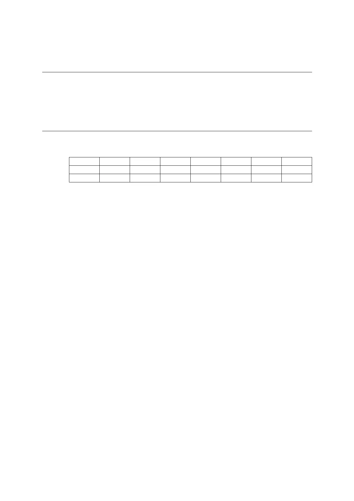
bit 7 6 5 4 3 2 1 0
Field TDR7 TDR6 TDR5 TDR4 TDR3 TDR2 TDR1 TDR0
Attribute R/W R/W R/W R/W R/W R/W R/W R/W
Initial value 0 0 0 0 0 0 0 0