MB95630H Series
MN702-00009-2v0-E FUJITSU SEMICONDUCTOR LIMITED 255
CHAPTER 14 LIN-UART
14.7 Registers
14.7.6 LIN-UART Extended Communication Control
Register (ECCR)
The LIN-UART extended communication control register (ECCR) is used for the
bus idle detection, the synchronous clock setting, and the LIN synch break
generation.
■ Register Configuration
■ Register Functions
[bit7] Reserved bit
Always set this bit to "0".
[bit6] LBR: LIN synch break generation bit
In operating mode 3, if this bit is set to "1", a LIN synch break whose length is specified in the LBL[1:0] bits
in the ESCR register is generated.
In operating mode 0/1/2, set this bit to "0".
[bit5] MS: Transmission side/reception side of serial clock select bit
This bit selects the transmission side/reception side of the serial clock in operating mode 2.
If the transmission side (MS = 0) is selected, the LIN-UART generates a synchronous clock.
If the reception side (MS = 1) is selected, the LIN-UART receives an external serial clock. In mode 0/1/3,
this bit is fixed at "0".
Modify this bit only when the SCR:TXE bit is "0".
Note: When the reception side is selected, select the external clock as the clock source and enable the
external clock input (SMR:SCKE = 0, EXT = 1, OTO = 1).
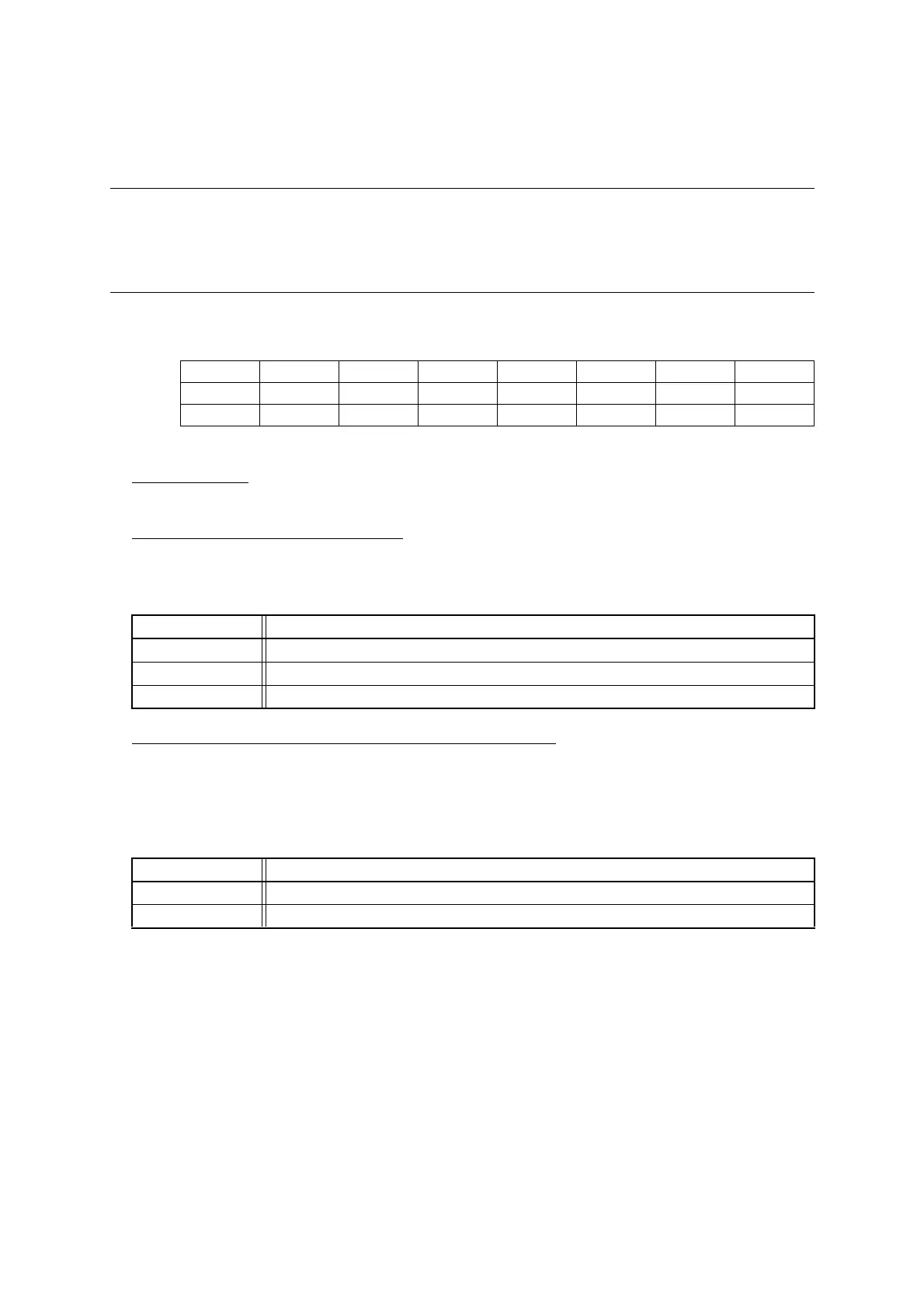
bit 7 6 5 4 3 2 1 0
Field Reserved LBR MS SCDE SSM Reserved RBI TBI
Attribute W W R/W R/W R/W W R R
Initial value 0 0 0 0 0 0 X X
bit6 Details (only for operating mode 3)
Read access The read value is always "0".
Writing "0" Has no effect on operation.
Writing "1" Generates a LIN synch break.
bit5 Details (only for operating mode 2)
Writing "0" Selects the transmission side (serial clock generation).
Writing "1" Selects the reception side (external serial clock reception).