MB95630H Series
MN702-00009-2v0-E FUJITSU SEMICONDUCTOR LIMITED 291
CHAPTER 17 CLOCK SUPERVISOR COUNTER
17.2 Configuration
17.2 Configuration
The clock supervisor counter consists of the following blocks:
• Control circuit
• Clock Monitoring Control Register (CMCR)
• Clock Monitoring Data Register (CMDR)
• Time-base timer output selector
• Counter source clock selector
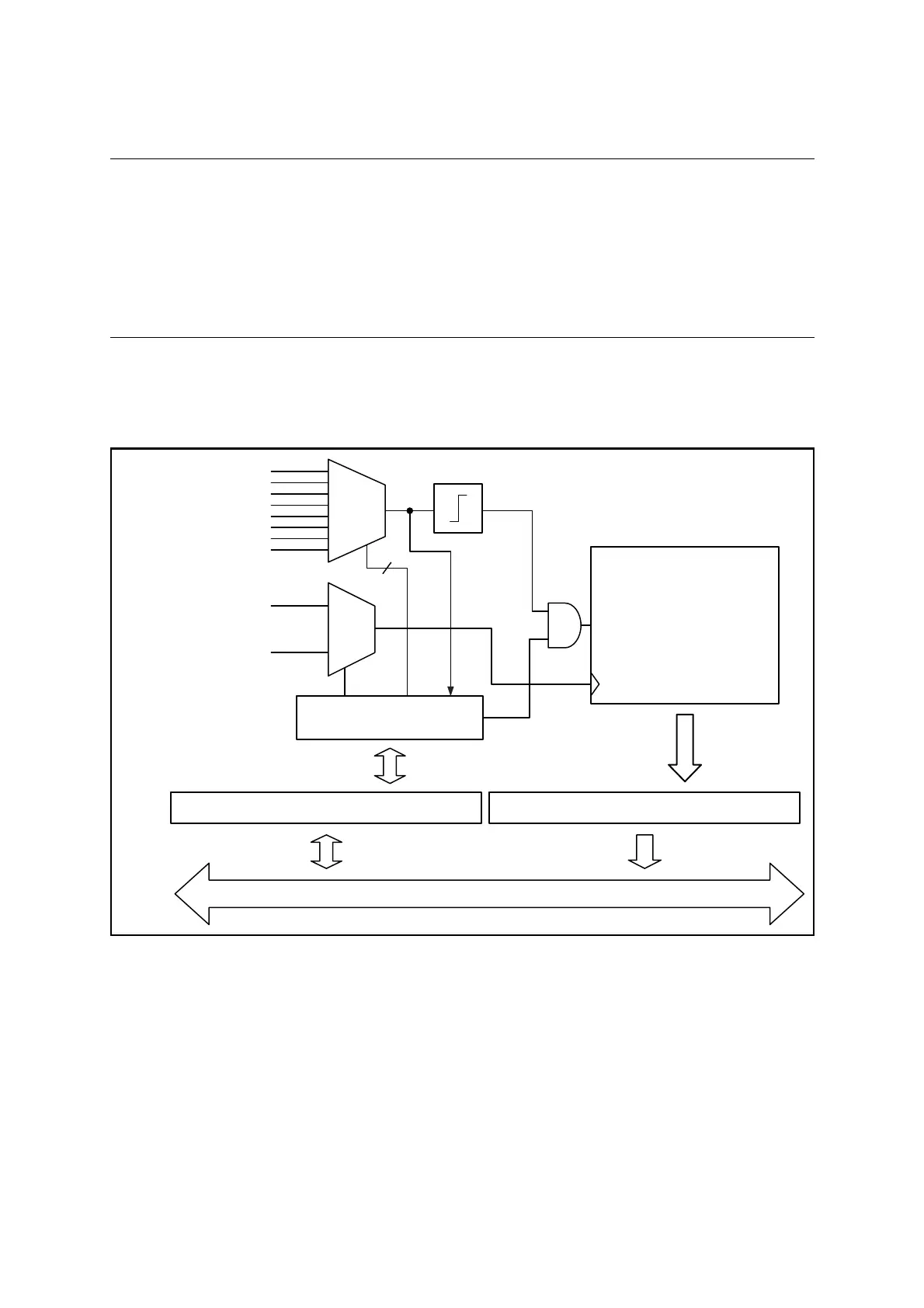
■ Block Diagram of Clock Supervisor Counter
Figure 17.2-1 is the block diagram of the clock supervisor counter.
Figure 17.2-1 Block Diagram of Clock Supervisor Counter
Time-base timer output
Main oscillation clock
Sub-oscillation clock
Edge detection
8-bit Counter
1st:
2nd:
counting starts
counting stops
Control Circuit
Clock Monitoring Control Register (CMCR) Clock Monitoring Data Register (CMDR)
CLK
Counter enabled
Internal Bus
3
Time-base
Timer
Output
Selector
Counter
Source
Clock
Selector