MB95630H Series
156 FUJITSU SEMICONDUCTOR LIMITED MN702-00009-2v0-E
CHAPTER 11 8/16-BIT COMPOSITE TIMER
11.12 Operation of Input Capture Function
11.12 Operation of Input Capture Function
This section describes the operation of the input capture function of the 8/16-
bit composite timer.
■ Operation of Input Capture Function
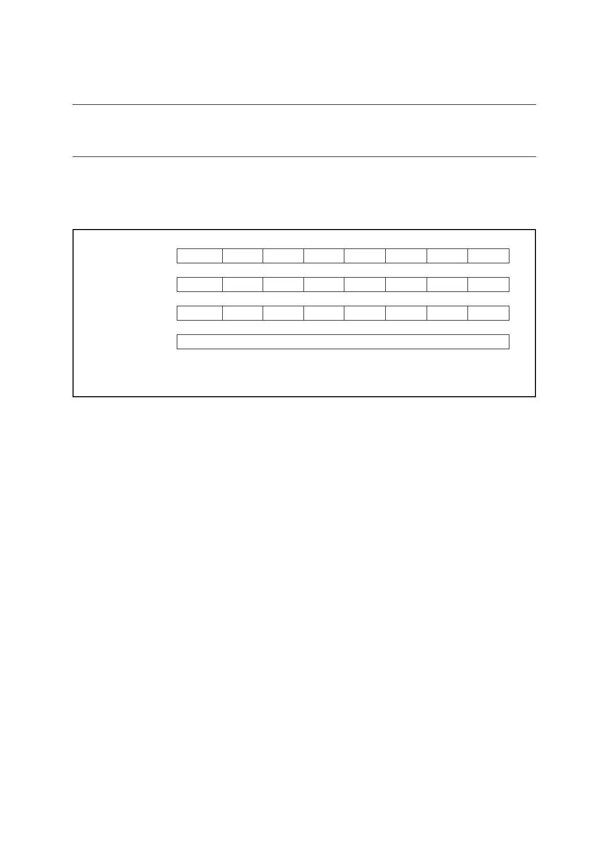
To use the input capture function, do the settings shown in Figure 11.12-1.
Figure 11.12-1 Settings for Input Capture Function
When the input capture function is selected, the counter value is stored to the 8/16-bit
composite timer data register (Tn0DR/Tn1DR) immediately after an edge of the external signal
input is detected. The target edge to be detected is selected by the timer operating mode select
bits (Tn0CR0/Tn1CR0:F[3:0]).
This function is available in free-run mode and clear mode, which can be selected by the timer
operating mode select bits.
In clear mode, the counter starts counting from "0x00". When an edge is detected, the counter
value is transferred to the 8/16-bit composite timer data register (Tn0DR/Tn1DR), the interrupt
flag (Tn0CR1/Tn1CR1:IR) is set to "1", and the counter returns to "0x00" and restarts
counting.
In free-run mode, when an edge is detected, the counter value is transferred to the 8/16-bit
composite timer data register (Tn0DR/Tn1DR) and the interrupt flag (Tn0CR1/Tn1CR1:IR) is
set to "1". In this case, the counter continues to count without being cleared.
This function has no effect on the buffer full flag (Tn0CR1/Tn1CR1:BF).
The time exceeding the range of the counter can be measured by counting the number of
counter overflows using the software. When the counter overflows, the interrupt flag (Tn0CR1/
Tn1CR1:IF) is set to "1". The interrupt service routine can therefore be used to count the
number of overflows. In addition, the timer output is inverted due to the overflow. The timer
output initial value can be set by the timer output initial value bit (Tn0CR1/Tn1CR1:SO).
bit7 bit6 bit5 bit4 bit3 bit2 bit1 bit0
Tn0CR0/Tn1CR0 IFE C2 C1 C0 F3 F2 F1 F0
❍ ❍❍❍❍❍❍❍
Tn0CR1/Tn1CR1 STA HO IE IR BF IF SO OE
1 ❍❍❍ × ❍ ××
TMCRn TO1 TO0 TIS MOD FE11 FE10 FE01 FE00
××❍❍❍❍❍❍
Tn0DR/Tn1DR Holds pulse width measurement value
❍: Bit to be used
×: Unused bit
1: Set to "1"