MB95630H Series
588 FUJITSU SEMICONDUCTOR LIMITED MN702-00009-2v0-E
CHAPTER 27 NON-VOLATILE REGISTER (NVR) INTERFACE
27.3 Registers
27.3.4 Watchdog Timer Selection ID Register
(Upper/Lower) (WDTH/WDTL)
This section describes the watchdog timer selection ID register (upper/lower)
(WDTH/WDTL).
■ Register Configuration
■ Functions of WDTH Register
[bit7:0] WDTH[7:0]: Watchdog timer selection ID (upper) bits
These bits are loaded from the Flash address 0xFFBE (bit7:0) after a reset. The initial values are determined
by the pre-loaded values in the NVR Flash area.
These bits cannot be modified while the CPU is running.
See Table 27.3-2 for watchdog timer selection.
See "27.5 Notes on Using NVR Interface" for notes on writing NVR values.
■ Functions of WDTL Register
[bit7:0] WDTL[7:0]: Watchdog timer selection ID (lower) bits
These bits are loaded from the Flash address 0xFFBF (bit7:0) after a reset. The initial values are determined
by the pre-loaded values in the NVR Flash area.
These bits cannot be modified while the CPU is running.
See Table 27.3-2 for watchdog timer selection.
See "27.5 Notes on Using NVR Interface" for notes on writing NVR values.
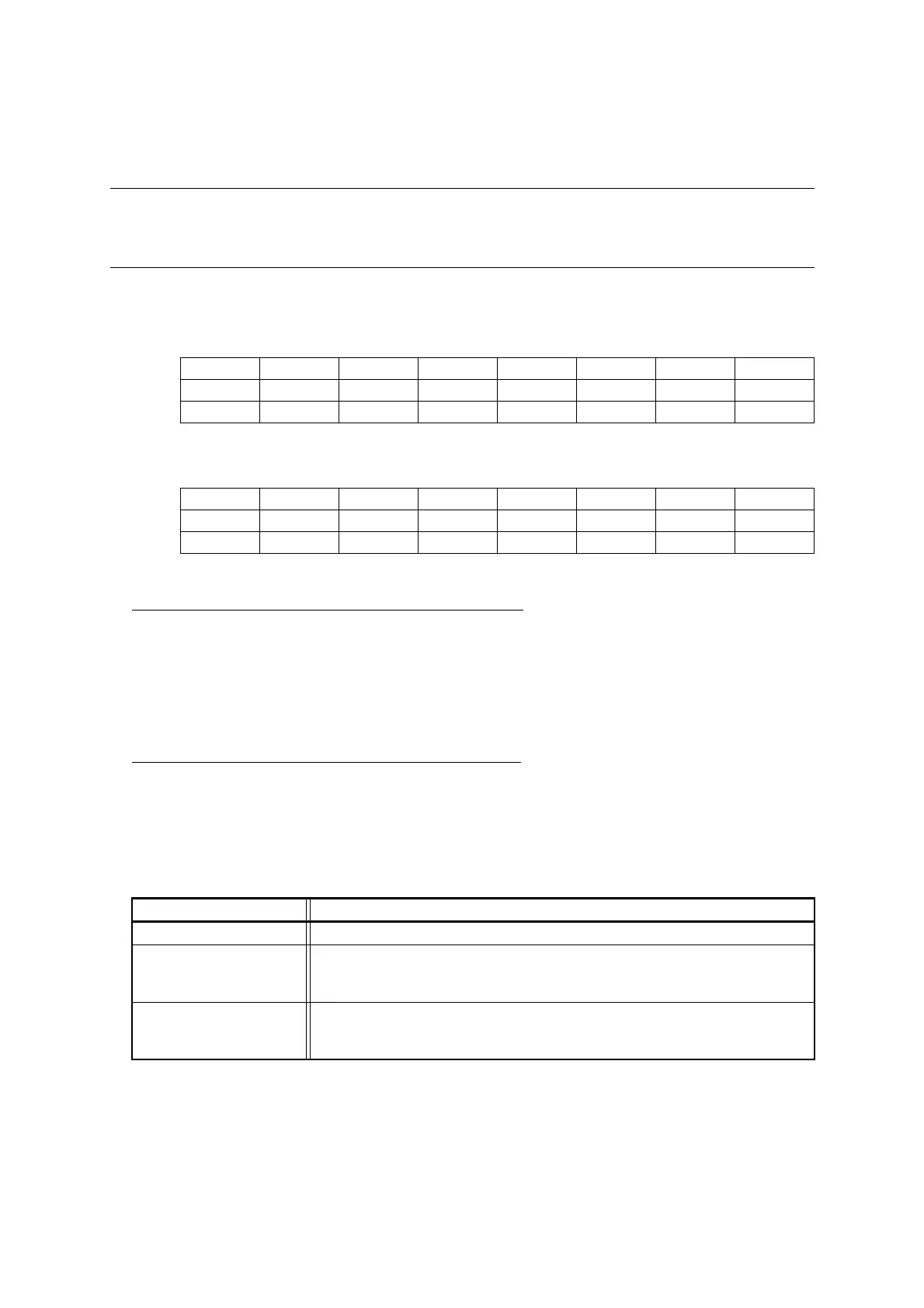
WDTH
bit 7 6 5 4 3 2 1 0
Field WDTH7 WDTH6 WDTH5 WDTH4 WDTH3 WDTH2 WDTH1 WDTH0
Attribute R R R R R R R R
Initial value X X X X X X X X
WDTL
bit 7 6 5 4 3 2 1 0
Field WDTL7 WDTL6 WDTL5 WDTL4 WDTL3 WDTL2 WDTL1 WDTL0
Attribute R R R R R R R R
Initial value X X X X X X X X
Table 27.3-2 Watchdog Timer Selection ID
WDTH[7:0], WDTL[7:0] Function
0xA596 The hardware watchdog timer is disabled; the software watchdog timer is enabled.
0xA597
The hardware watchdog timer is enabled; the software watchdog timer is disabled. The
hardware watchdog timer can be stopped in all standby modes (stop mode, sleep mode,
time-base timer mode and watch mode).
Other than the above
The hardware watchdog timer is enabled; the software watchdog timer is disabled. The
hardware watchdog timer keeps operating in all standby modes (stop mode, sleep mode,
time-base timer mode and watch mode).