MB95630H Series
MN702-00009-2v0-E FUJITSU SEMICONDUCTOR LIMITED 177
CHAPTER 12 EXTERNAL INTERRUPT CIRCUIT
12.2 Configuration
12.2 Configuration
The external interrupt circuit consists of the following blocks:
• Edge detection circuit
• External interrupt control register
■ Block Diagram of External Interrupt Circuit
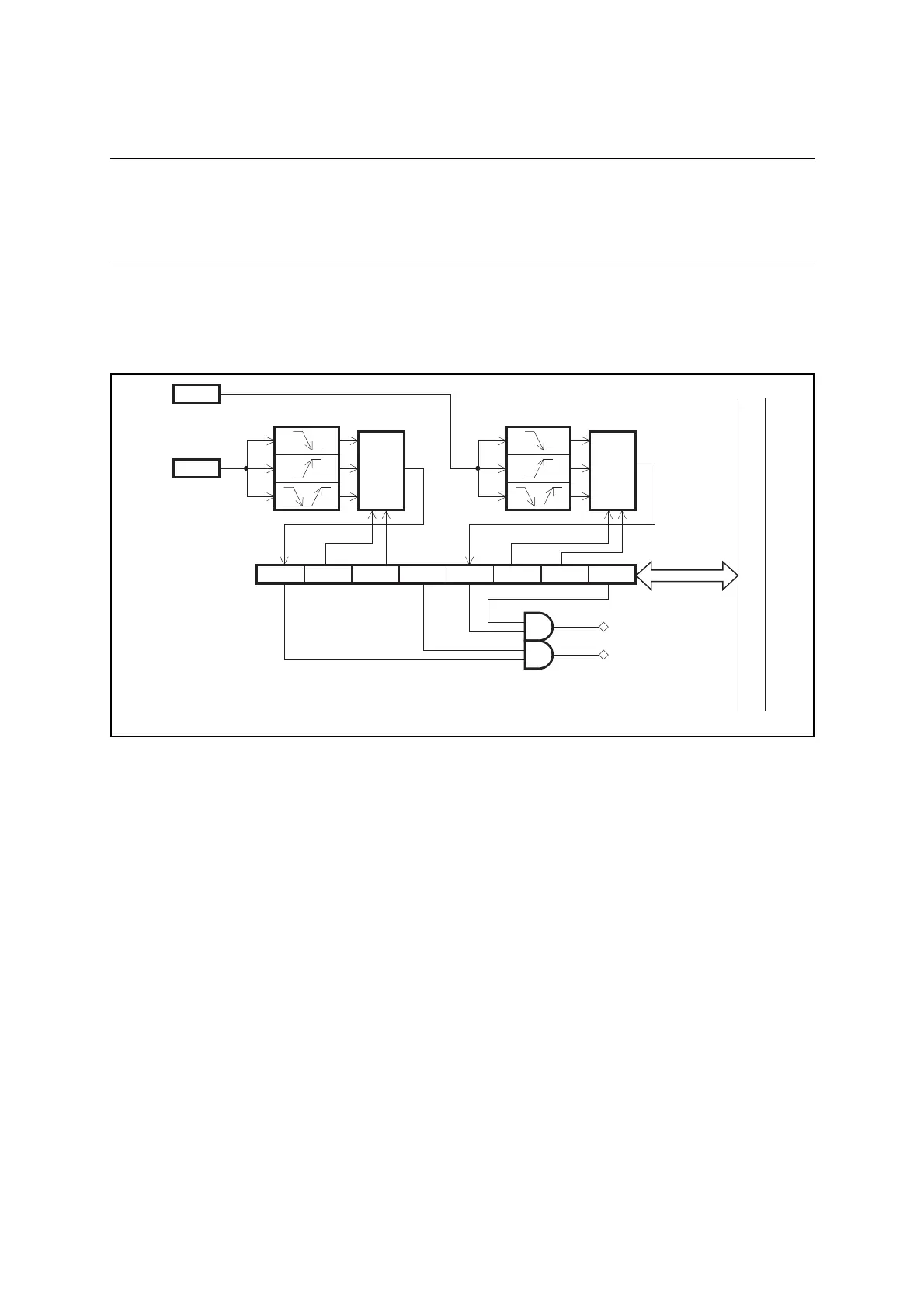
Figure 12.2-1 is the block diagram of the external interrupt circuit.
Figure 12.2-1 Block Diagram of External Interrupt Circuit
● Edge detection circuit
When the polarity of the edge detected on a signal input to an external interrupt circuit pin
(INT) matches the polarity of the edge selected in the interrupt control register (EIC), a
corresponding external interrupt request flag bit (EIR) is set to "1".
● External interrupt control register (EIC)
This register is used to select an edge, enable or disable interrupt requests, check for interrupt
requests, etc.
EIR1 SL11 SL10 EIE1 EIR0 SL01 SL00 EIE0
External interrupt
control register
(EIC)
Note: Pin names and interrupt request numbers vary among products.
For details, refer to “■ PIN FUNCTIONS” and “■ INTERRUPT SOURCE TABLE”
in the device data sheet.
INTn
Pin
INTn+1
Pin
10
01
11
Selector
10
01
11
Selector
IRQXX
IRQXX
Internal data bus
Edge detection circuit 0Edge detection circuit 1