MB95630H Series
MN702-00009-2v0-E FUJITSU SEMICONDUCTOR LIMITED 237
CHAPTER 14 LIN-UART
14.6 Operations of LIN-UART and LIN-UART
Setting Procedure Example
14.6.6 Master/Slave Mode Communication Function
(Multiprocessor Mode)
Operating mode 1 allows communication among multiple CPUs connected in
master/slave mode. The LIN-UART can be used as a master or a slave.
■ Master/Slave Mode Communication Function
To operate the LIN-UART in multiprocessor mode (operating mode 1), the settings shown in
Figure 14.6-13 are required.
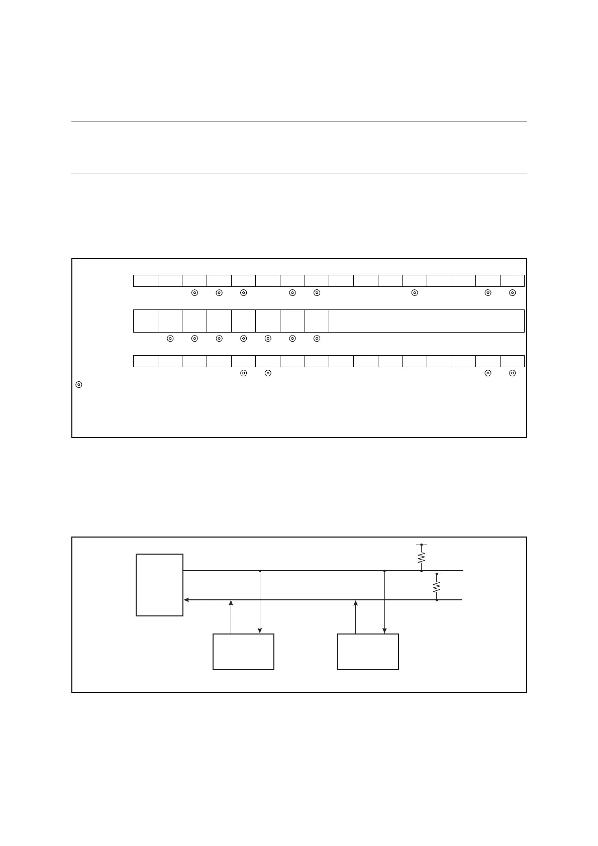
Figure 14.6-13 Settings of LIN-UART Operating Mode 1
● Inter-CPU connection
For master/slave mode communication, a communication system consists of two common
communication lines connecting between one master CPU and multiple slave CPUs as shown
in Figure 14.6-14. The LIN-UART can be used as a master or a slave.
Figure 14.6-14 Connection Example of LIN-UART Master/Slave Mode Communication
● Function selection
In master/slave mode communication, select the operating mode and the data transfer method
as shown in Figure 14.6-14.
bit15 bit14 bit13 bit12 bit11 bit10 bit9 bit8 bit7 bit6 bit5 bit4 bit3 bit2 bit1 bit0
SCR, SMR PEN P SBL CL AD CRE RXE TXE MD1 MD0 OTO EXT
REST UPCL SCKE
SOE
Mode 1 → +× 0 010 00
SSR,
RDR/TDR
PE ORE FRE
RDRF
TDRE
BDS RIE TIE
Set compare data (during writing)
Retain receive data (during reading)
Mode 1 → ×
ESCR, ECCR LBIE LBD LBL1 LBL0
SOPE
SIOP CCO
SCES
Reserved
LBR MS
SCDE
SSM
Reserved
RBI TBI
Mode 1 → ×××× 000××××0
: Bit to be used
× : Unused bit
1 : Set to "1"
0 : Set to "0"
+ : Bit correctly set automatically
Master CPU
Slave CPU #0
Slave CPU #1