MB95630H Series
438 FUJITSU SEMICONDUCTOR LIMITED MN702-00009-2v0-E
CHAPTER 21 MULTI-PULSE GENERATOR
21.6 Registers
21.6.4.2 16-bit MPG Output Data Buffer Register (Lower)
(OPDBRLx)
The 16-bit MPG output data buffer register (lower) (OPDBRLx) selects the
waveform to be output to the OPT3 to OPT0 pins.
■ Register Configuration
■ Register Functions
[bit7:6] OP3[1:0]: OPT3 output waveform select bits
These bits select the output waveform to the OPT3 pin.
The waveform selected is to be output to the OPT3 pin after the data in the OPDBRHx/OPDBRLx specified
in the BNKF bit and RDA[2:0] bits is loaded to the OPDUR/OPDLR register.
[bit5:4] OP2[1:0]
: OPT2 output waveform select bits
These bits select the output waveform to the OPT2 pin.
The waveform selected is to be output to the OPT2 pin after the data in the OPDBRHx/OPDBRLx specified
in the BNKF bit and RDA[2:0] bits is loaded to the OPDUR/OPDLR register.
[bit3:2] OP1[1:0]
: OPT1 output waveform select bits
These bits select the output waveform to the OPT1 pin.
The waveform selected is to be output to the OPT1 pin after the data in the OPDBRHx/OPDBRLx specified
in the BNKF bit and RDA[2:0] bits is loaded to the OPDUR/OPDLR register.
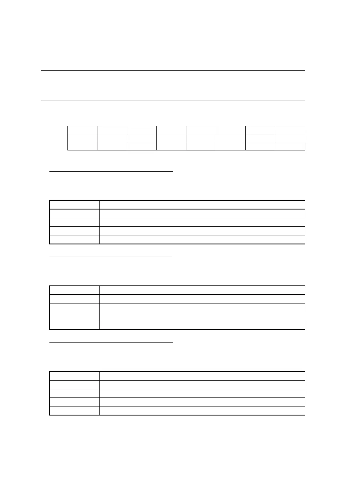
bit 7 6 5 4 3 2 1 0
Field OP31 OP30 OP21 OP20 OP11 OP10 OP01 OP00
Attribute R/W R/W R/W R/W R/W R/W R/W R/W
Initial value 0 0 0 0 0 0 0 0
bit7:6 Details
Writing "00" Selects "L" level as the waveform to be output to the OPT3 pin.
Writing "01" Selects the output of the PPG timer as the waveform to be output to the OPT3 pin.
Writing "10" Selects the inverted output as the waveform to be output to the OPT3 pin.
Writing "11" Selects "H" level as the waveform to be output to the OPT3 pin.
bit5:4 Details
Writing "00" Selects "L" level as the waveform to be output to the OPT2 pin.
Writing "01" Selects the output of the PPG timer as the waveform to be output to the OPT2 pin.
Writing "10" Selects the inverted output as the waveform to be output to the OPT2 pin.
Writing "11" Selects "H" level as the waveform to be output to the OPT2 pin.
bit3:2 Details
Writing "00" Selects "L" level as the waveform to be output to the OPT1 pin.
Writing "01" Selects the output of the PPG timer as the waveform to be output to the OPT1 pin.
Writing "10" Selects the inverted output as the waveform to be output to the OPT1 pin.
Writing "11" Selects "H" level as the waveform to be output to the OPT1 pin.