MB95630H Series
MN702-00009-2v0-E FUJITSU SEMICONDUCTOR LIMITED 367
CHAPTER 20 16-BIT RELOAD TIMER
20.6 Operations and Setting Procedure Example
20.6.2 Event Count Mode
In this mode, the 16-bit downcounter counts down each time the valid edge is
detected on the pulses input to the TIn pin, and an interrupt request is output
to the interrupt controller when an underflow occurs ("0x0000" → "0xFFFF"). In
addition, a toggle waveform or square waveform can be output from the TOn
pin.
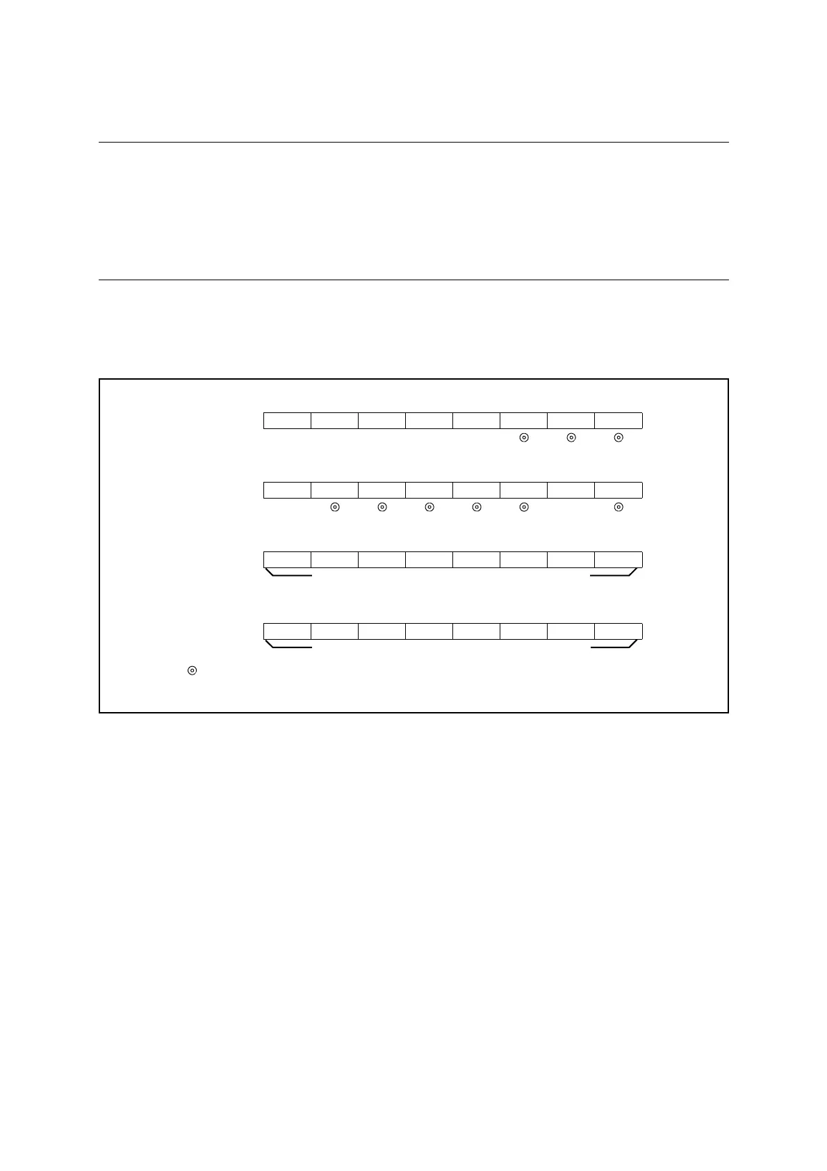
■ Event Count Mode Setup
The timer requires the register settings shown in Figure 20.6-9 to operate as an event counter.
Figure 20.6-9 Event Count Mode Setup
■ Event Count Mode
The value set in the 16-bit reload timer reload register ch. n (TMRLRHn/TMRLRLn) is
reloaded to the 16-bit counter when the count enable bit (CNTE) is set to "1" and the software
trigger bit (TRG) is set to "1". The counter counts each time the valid edge (rising, falling, or
both edges selectable) is detected on the pulses input to the TIn pin (external count clock).
● Operation of reload mode
If the reload select bit (RELD) is "1", the value set in the 16-bit reload timer reload register
ch. n (TMRLRHn/TMRLRLn) is reloaded to the 16-bit counter and the count continues when
the 16-bit counter underflows ("0x0000" → "0xFFFF").
The underflow interrupt request flag bit (UF) in the 16-bit reload timer control status register
(lower) ch. n (TMCSRLn) is set to "1" when an underflow occurs ("0x0000" → "0xFFFF") in
the 16-bit counter, and an interrupt request is output if the underflow interrupt enable bit
(INTE) is set to "1".
The TOn pin can output a toggle waveform that is inverted each time an underflow occurs.
Figure 20.6-10 shows the count operation in reload mode.
bit7 bit6 bit5 bit4 bit3 bit2 bit1 bit0
TMCSRHn - - CSL2 CSL1 CSL0 MOD2 MOD1 MOD0
111
bit7 bit6 bit5 bit4 bit3 bit2 bit1 bit0
TMCSRLn - OUTE OUTL RELD INTE UF CNTE TRG
1
bit7 bit6 bit5 bit4 bit3 bit2 bit1 bit0
TMRLRHn D15 D14 D13 D12 D11 D10 D9 D8
bit7 bit6 bit5 bit4 bit3 bit2 bit1 bit0
TMRLRLnD7D6D5D4D3D2D1D0
: Used bit
1 : Set to "1"
Set initial value of counter (reload value) (upper)
Set initial value of counter (reload value) (lower)