MB95630H Series
366 FUJITSU SEMICONDUCTOR LIMITED MN702-00009-2v0-E
CHAPTER 20 16-BIT RELOAD TIMER
20.6 Operations and Setting Procedure Example
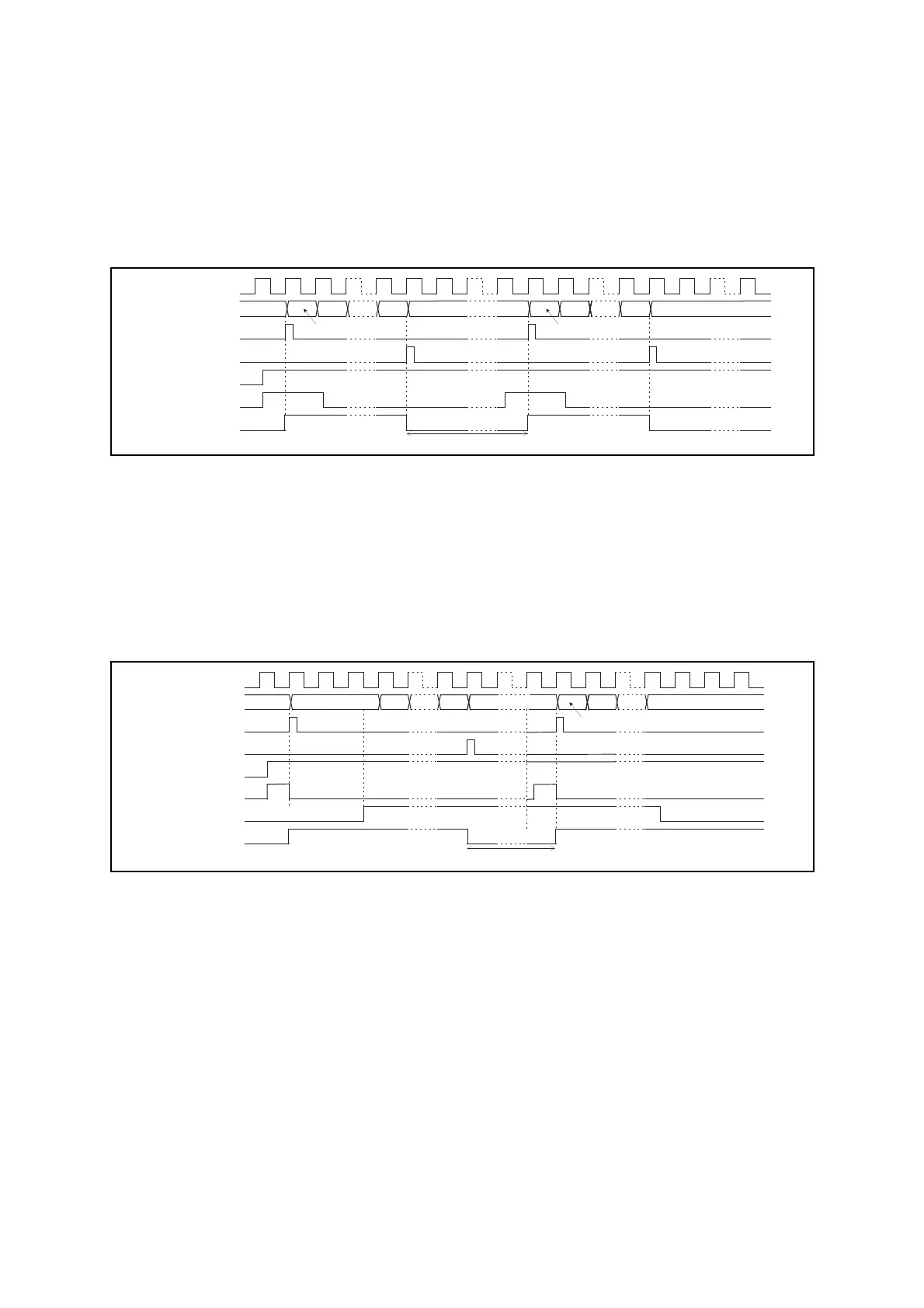
● External trigger input
The count starts when the count enable bit (CNTE) is "1" and the valid edge of trigger input
(rising, falling, or both edges) specified by the operating mode select bits (MOD[2:0]) is input
to the TIn pin.
Figure 20.6-7 shows the external trigger input operation in one-shot mode.
Figure 20.6-7 Count Operation in One-shot Mode (External Trigger Input Operation)
● Gate input operation
The count starts when the count enable bit (CNTE) is "1" and the software trigger bit (TRG) is
also set to "1".
The timer continues counting as long as the trigger input enable level ("L" or "H" selectable)
specified by the operating mode select bits (MOD[2:0]) is input to the TIn pin.
Figure 20.6-8 shows the external gate input operation in one-shot mode.
Figure 20.6-8 Count Operation in One-shot Mode (External Gate Input Operation)
Count clock
Counter
-1
0000
-1
0000
Data load signal
UF bit
CNTE bit
TIn pin
TOn pin
Reload data Reload data
FFFF FFFF
Wait for start trigger input
Count clock
Counter
Data load signal
UF bit
CNTE bit
TIn pin
TOn pin
Reload data
Reload data
TRG bit
-1
0000 FFFF
-1 -1
Wait for start trigger input