MB95630H Series
MN702-00009-2v0-E FUJITSU SEMICONDUCTOR LIMITED 199
CHAPTER 14 LIN-UART
14.1 Overview
The LIN-UART operates in four different modes. The operating mode is selected by the MD0
and MD1 bits in the LIN-UART serial mode register (SMR). Operating mode 0 and operating
mode 2 are used for bi-directional serial communication; operating mode 1 for master/slave
communication; and operating mode 3 for LIN master/slave communication.
The MD0 and MD1 bits in the LIN-UART serial mode register (SMR) are used to select the
following LIN-UART operating modes.
• Operating mode 1 supports both master and slave operation for the multiprocessor mode.
• The communication format of operating mode 3 is fixed: 8-bit data, no parity, stop bit 1,
LSB-first.
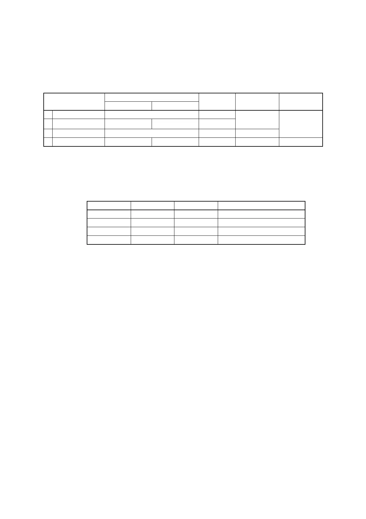
Table 14.1-2 LIN-UART Operating Modes
Operating mode
Data length
Synchronous
method
Stop bit length Data bit format
No parity With parity
0 Normal mode 7 bits or 8 bits Asynchronous
1 bit or 2 bits
LSB first
MSB first
1 Multiprocessor mode
7 bits or 8 bits +1
*
- Asynchronous
2 Normal mode 8 bits Synchronous None, 1 bit, 2 bits
3 LIN mode 8 bits - Asynchronous 1 bit LSB first
- : Unavailable
* : "+1" is the address/data select bit (AD) used for communication control in multiprocessor mode.
Table 14.1-3 LIN-UART Operating Modes
MD1 MD0 Operating mode Type
0 0 0 Asynchronous (Normal mode)
0 1 1 Asynchronous (Multiprocessor mode)
1 0 2 Synchronous (Normal mode)
1 1 3 Asynchronous (LIN mode)