MB95630H Series
226 FUJITSU SEMICONDUCTOR LIMITED MN702-00009-2v0-E
CHAPTER 14 LIN-UART
14.6 Operations of LIN-UART and LIN-UART
Setting Procedure Example
● Stop bit and reception bus idle flag
For transmission, the number of stop bits can be selected from one and two. If two stop bits are
selected, both stop bits are detected during reception.
When the first stop bit is detected, the receive data register full flag bit (SSR:RDRF) is set to
"1". When no start bit is detected afterward, the receive bus idle flag bit (ECCR:RBI) is set to
"1", indicating that no reception is executed.
● Error detection
In operating mode 0, the parity error, the overrun error and the frame error can be detected.
In operating mode 1, the overrun error and the frame error can be detected. However, the parity
error cannot be detected.
● Parity
The addition (at transmission) of and the detection (during reception) of a parity bit can be set.
The parity enable bit (SCR:PEN) is used to select whether or not to use a parity; the parity
select bit (SCR:P) is used to select the odd/even parity.
In operating mode 1, the parity cannot be used.
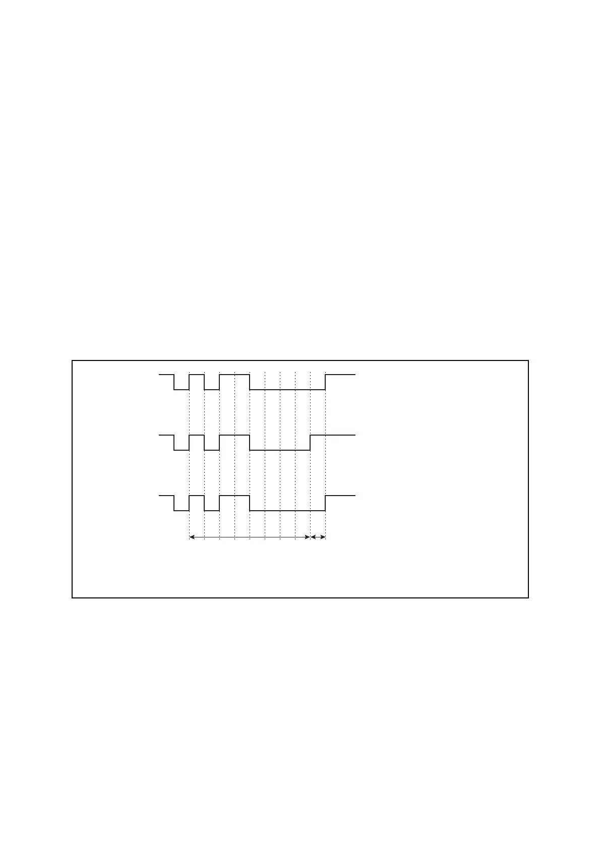
Figure 14.6-2 Transmission Data when Parity is Enabled
● Data signaling
NRZ data format.
● Data bit transfer method
The data bit transfer method can be LSB-first transfer or MSB-first transfer.
SIN
1011 000
SOT
1011 001
SOT
1011 000
ST SP
ST SP
ST SP
0
0
0
0
0
0
A parity error occurs in even
parity during reception
(SCR:P = 0)
Transmission of even parity
(SCR:P = 0)
Transmission of odd parity
(SCR:P = 1)
ST: Start bit, SP: Stop bit, Parity used (PEN = 1)
Note: In operating mode 1, the parity cannot be used.
Parity
Data