MB95630H Series
MN702-00009-2v0-E FUJITSU SEMICONDUCTOR LIMITED 233
CHAPTER 14 LIN-UART
14.6 Operations of LIN-UART and LIN-UART
Setting Procedure Example
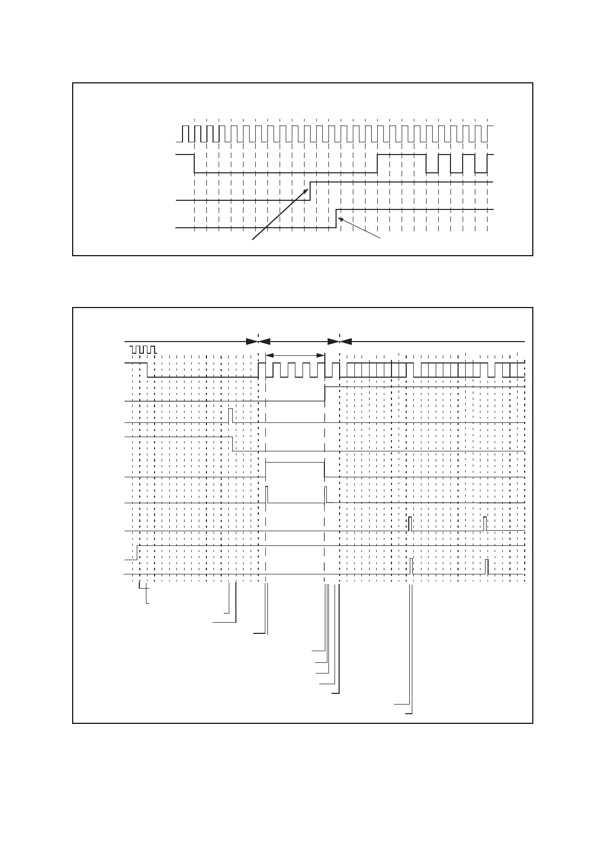
Figure 14.6-8 LIN-UART Operation in LIN Slave Mode
● LIN bus timing
Figure 14.6-9 LIN Bus Timing and LIN-UART Signals
FRE
(RXE = 1)
LBD
(RXE = 0)
Serial clock cycle#
Serial clock
Serial input
(LIN bus)
Receive interrupt generated when RXE = 1 Receive interrupt generated when RXE = 0
0123 45678 9 10111213 14 15
bus
RXE
LBD
(IRQ)
RDRF
(SIN)
(IRQ)
IRQ(TII0)
LIN
LBIE
RIE
8/16-bit composite timer count
No clock
(Calculation frame)
Previous serial clock
Newly calculated s erial clock
Enable receive
interrupts
LIN break starts
LIN break detected, interrupt generated
IRQ clear by CPU (LBD → 0)
IRQ clear: input capture of 8/16-bit composite timer count starts
IRQ clear: Baud rate calculated and set
LBIE disabled
Reception enabled
Falling edge of start bit
1 byte of reception data saved to RDR
RDR read by CPU
RDR read
by CPU
TII0 input
(LSYN)
IRQ (8/16-bit composite timer)
IR
Q (8/16-bit composite timer)