MB95630H Series
MN702-00009-2v0-E FUJITSU SEMICONDUCTOR LIMITED 247
CHAPTER 14 LIN-UART
14.7 Registers
[bit2] UPCL: LIN-UART programmable clear bit (LIN-UART software reset)
This bit resets the LIN-UART.
Writing "0" to this bit has no effect on operation.
Writing "1" to this bit resets the LIN-UART immediately (LIN-UART software reset). However, the register
settings are maintained. Upon the reset, transmission and reception are suspended, and all of the transmit/
receive interrupt sources (TDRE, RDRF, LBD, PE, ORE, FRE) are cleared.
Reset the LIN-UART after disabling the interrupt and transmission.
In addition, after the LIN-UART is reset, the receive data register is cleared (RDR = 0x00), and the reload
counter is restarted.
[bit1] SCKE: LIN-UART serial clock output enable bit
This bit controls the I/O port of the LIN-UART serial clock.
Writing "0" to this bit makes the SCK pin function as a general-purpose I/O port or a LIN-UART serial clock
input pin.
Writing "1" to this bit makes the SCK pin function as a LIN-UART serial clock output pin and output the
clock in operating mode 2 (synchronous).
When set as a serial clock output pin (SCKE = 1), the SCK pin functions as a LIN-UART serial clock output
pin regardless of the state of the general-purpose I/O port sharing the same pin with SCK.
Note: To use the SCK pin as a LIN-UART serial clock input pin (SCKE = 0), enable the use of the input port
by setting the bit in the DDR register corresponding to the general-purpose I/O port sharing the same
pin with SCK. In addition, select the external clock (EXT = 1) using the external serial clock source
select bit.
[bit0] SOE: LIN-UART serial data output enable bit
This bit enables or disables outputting LIN-UART serial data.
When set as a serial data output pin (SOE = 1), the SOT pin functions as a serial data output pin (SOT)
regardless of the state of the general-purpose I/O port sharing the same pin with SOT.
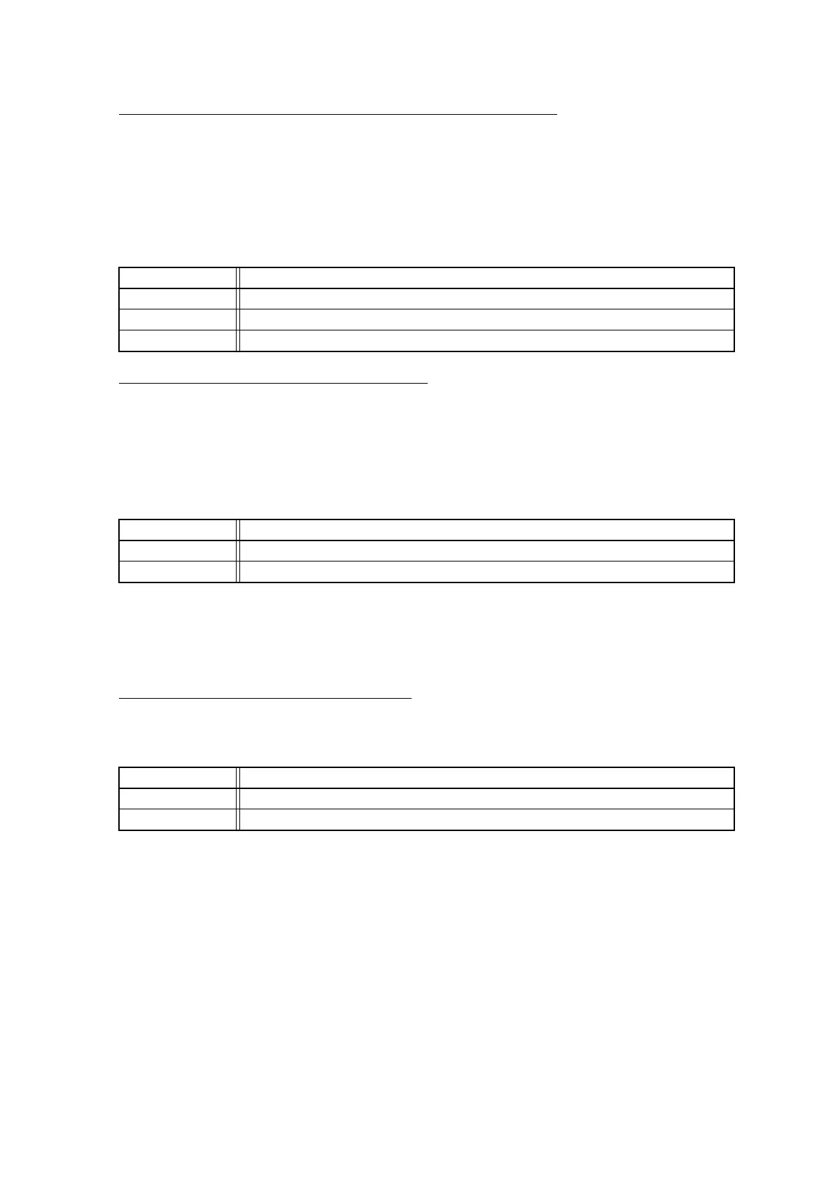
bit2 Details
Read access The read value is always "0".
Writing "0" Has no effect on operation.
Writing "1" Resets the LIN-UART.
bit1 Details
Writing "0" Makes the SCK pin function as a general-purpose I/O port or a LIN-UART serial clock input pin.
Writing "1" Makes the SCK pin function as a LIN-UART serial clock output pin.
bit0 Details
Writing "0" Makes the SOT pin function as a general-purpose I/O port.
Writing "1" Makes the SOT pin function as the LIN-UART serial data output pin.