MB95630H Series
388 FUJITSU SEMICONDUCTOR LIMITED MN702-00009-2v0-E
CHAPTER 21 MULTI-PULSE GENERATOR
21.2 Block Diagram
■ Block Diagram of Position Detection Circuit
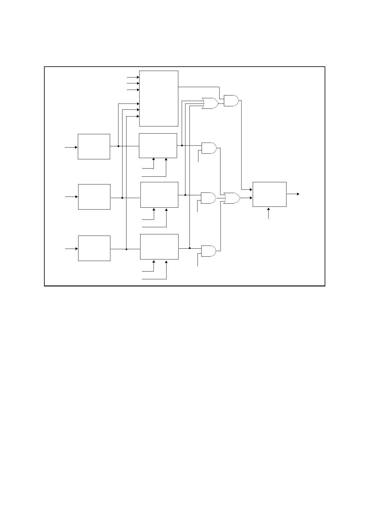
Figure 21.2-5 Block Diagram of Position Detection Circuit
● Comparison circuit
The comparison circuit is used to compare the level of the position detection input (SNI2 to
SNI0) with RDA[2:0] bits in the 16-bit MPG output data register (upper) (OPDUR). If the
selector is selected, a data write time output signal is generated when a match is detected.
● Edge detect circuit 0, 1, 2
Edge detect circuit 0, 1 and 2 are identical.
The edge detect circuit is used to compare the edge of the position input (SNI2 to SNI0) with 3
different kind of edge setting. If the selector is selected, a data write time output signal is
generated when an effective edge is detected at the one of SNI2 to SNI0 inputs.
● Noise filter
The noise filter is used to filter out the noise of the input signal in which there are 4 kind of
sampling clock for selection.
● Selector
The selector is used to select from either edge detect circuit or comparison circuit to generate
data write time output signal to the data write control unit.
COMPARISON
NOISE
CIRCUIT
WTIN1
RDA2
SELECTOR
EDGE
DETECTION
CPE1
CPE0
FILTER
CIRCUIT
RDA1
RDA0
CIRCUIT 0
EDGE
DETECTION
CIRCUIT 1
EDGE
DETECTION
CIRCUIT 2
NOISE
FILTER
CIRCUIT
NOISE
FILTER
CIRCUIT
CMPE
CPE1
CPE0
CPE1
CPE0
SNI0
SNI1
SNI2
SEE2
SEE1
SEE0