MB95630H Series
466 FUJITSU SEMICONDUCTOR LIMITED MN702-00009-2v0-E
CHAPTER 22 UART/SIO
22.6 Operations and Setting Procedure Example
● Receive error in clock asynchronous mode (UART)
If any of the following three error flags (PER, FER, OVE) has been set, receive data is not
transferred to the UART/SIO serial input data register ch. n (RDRn) and the receive data
register full flag bit (RDRF) is not set to "1" either.
• Parity error (PER)
The parity error bit (PER) is set to "1" if the parity bit in received serial data does not match
the parity polarity bit (TDP) when the parity control bit (PEN) contains "1".
• Framing error (FER)
The framing error bit (FER) is set to "1" if "1" is not detected at the position of the first stop
bit in serial data received in the set character bit length (CBL) under parity control (PEN).
Note that the stop bit is not checked if it appears at the second bit or later.
• Overrun error (OVE)
Upon completion of reception of serial data, the overrun error bit (OVE) is set to "1" if the
reception of the next data is performed before the previous receive data is read.
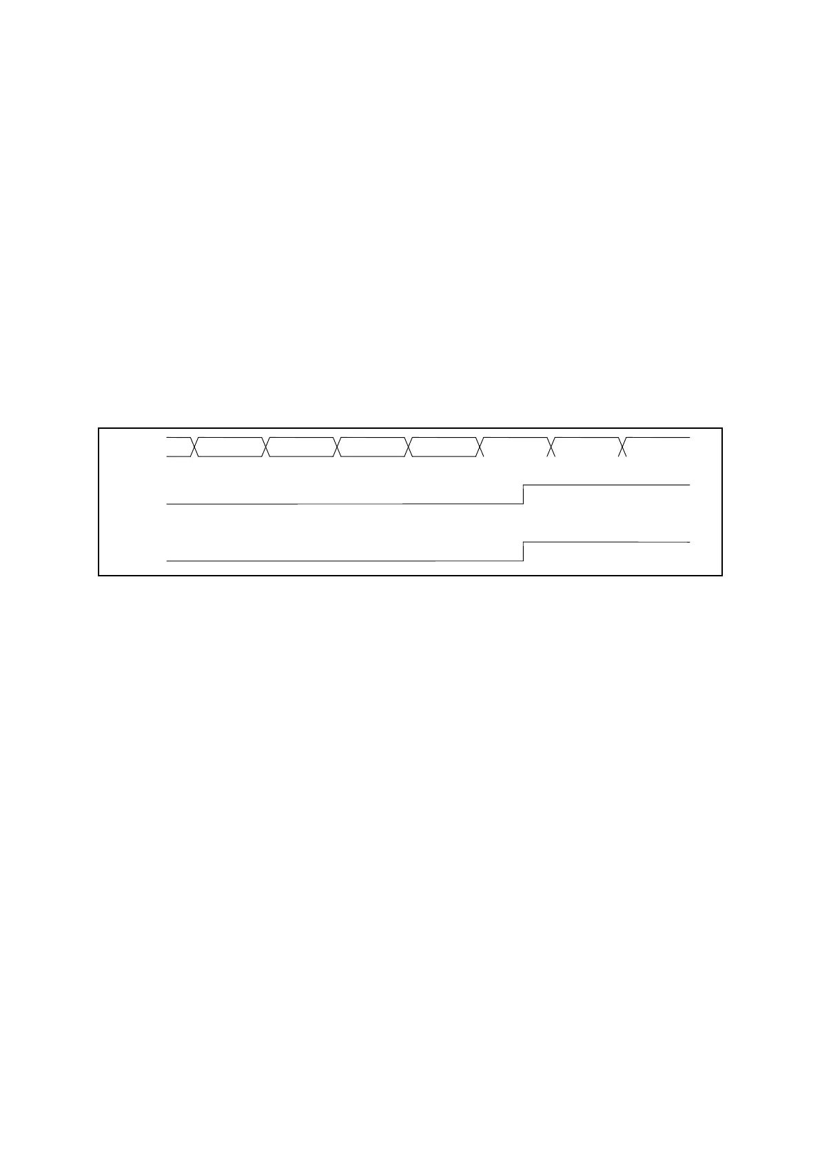
Each flag is set at the position of the first stop bit.
Figure 22.6-4 Setting Timing for Receive Errors
UIn D5 D6 D7 P SP
SP
PER
OVE
FER
Receive
interrupt